

Hardware components | ||||||
| × | 1 | ||||
| × | 1 | ||||
Software apps and online services | ||||||
| ||||||
| ||||||
 |
| |||||
Hand tools and fabrication machines | ||||||
| ||||||
| ||||||
Info:
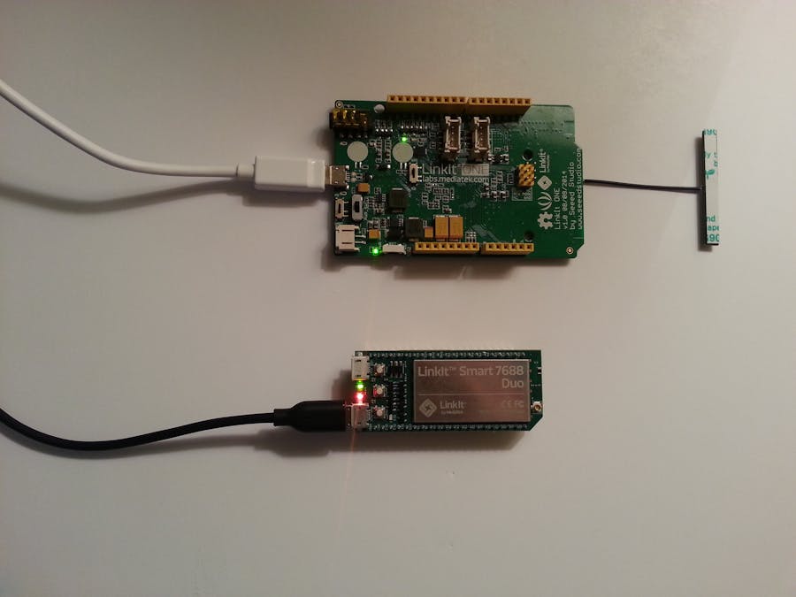
I will be building a sensor monitoring system using a MediaTek LinkIt™ Smart 7688 combined with MediaTek LinkIt ONE for continuous live wireless monitoring and communication between multiple devices anywhere in the home. Additionally the LinkIt ONE will have auto configuration, making any device on the network which has a LinkIt MT processor plug-and-play without any add-ons/shields. The system will be accessible via a smart device with an app (Currently an html file). Since this a brand new device, this tutorial will include how to connect to an IoT cloud and an initial setup, so that you can hit the ground running with the awesome LinkIt Smart 7688. I am usually very skeptical of about micro-controllers and this one nailed it. One of my favorite parts is the fact that this micro-controller has OpenWRT, making wireless configurations amazingly easy and with the support of wireless flashing and updating itself, so all you need to start is the micro-usb cable for power.
Required:
- LinkIt Smart 7688
- Micro USB cables
- LinkIt ONE
- A PC (Preferably windows)
- Breadboard
- Male to Female/Male to Male jumper wires
- 2x16 LCD
- 2 Potentiometers
- Ultrasonic sensor
- Home with network capabilities
- Some pre-knowledge of command line(Linux). Don't worry I put in a lot of details
- Time... (Might take you about and hour or two)
Set-up:
Obviously this is a brand new device, so here are the instructions on how to install/configure/update the new LinkIt Smart 7688 to your computer. (Images from original PDF)
Before getting started, it's a good idea to check these out to get more familiar with the LinkIt Smart 7688:
MediaTek LinkIt Smart Duo Quick Start Guide
MediaTek%20LinkIt%20Smart%207688%20Duo%20Quick%20Start%20Guide.pdf
MediaTek LinkIt Smart Quick Start Guide
MediaTek%20LinkIt%20Smart%207688%20Quick%20Start%20Guide.pdf
MediaTek LinkIt Smart Developer's Guide
MediaTek%20LinkIt%20Smart%207688%20Developers%20Guide%20v_0.92.pdf
- Make sure you have a Linkit Smart 7688 with you and a micro USB cable
- Install, Bonjour Print service (Windows only): https://support.apple.com/kb/DL999?locale=en_US
- Install PuTTy (Windows only): http://www.chiark.greenend.org.uk/~sgtatham/putty/download.html
- Install WinSCP (Windows): https://winscp.net/eng/download.php
- Make sure the LED for wireless is on
- Go to your wireless settings on the computer and connect to the SSID with LinkIt Smart 7688:
- Go into your browser (Microsoft Edge didn't work for me, try Chrome)
- Enter: http://mylinkit.local/
- Don't put anything for the account and just type in a password
- The page will refresh and it'll ask for you to enter in your password again, do that exactly
Update:
- To update the Linkit Smart 7688 you will need to have the SDK download, you can download it at the official Mediatek Downloads page
- Login in into: http://mylinkit.local/
- Scroll down until you see "Upgrade Firmware"
- When I tried re-flashing the Linkit Smart 7688, it took me about 3-4 minutes, so DO NOT unplug during that time, or it could not boot up again.
Set-up part 2:
- Open up PuTTy (For Mac/Linux find a SSH client or use this command in terminal: 'ssh root@myLinkIt.local')
- Press the SSH radio button and type in the input box "myLinkIt.local"
- Keep port at 22
- I would save this because we are going to use this often, so next time you can just load the settings and run
- Connect to that, and you should get the linux console for the Linkit Smart 7688
- Awesome right? A whole linux terminal...
Test out the above system by running the command
python /IoT/examples/blink-gpio44.py
Press Ctrl+c when wanting to quit blinking the WiFi LED every 500 milliseconds
For the next steps for the actual project you will need the LinkIt Smart 7688 Duo HDK, with the second micro controller.
Set-up part 2.5:
Now we want WinSCP for easy file transfer to the LinkIt Smart 7688
- Download WinSCP using the link above
- Press English (If option)
- Select next on welcome screen
- Then Accept
- Choose Typical installation
- Then Commander
- Press Install
- It might ask, that you already have stored sessions in PuTTy, press accept
- Next window uncheck the Open Getting started page
- Now WinSCP should popup, if you don't already see the PuTTy device, press new site and put host name as
myLinkIt.local - User name =
root - Password = Whatever you put earlier
- MAKE SURE YOU SET THE MODE FROM SFTP to SCP
- If you do see your device, just add a username and password to the input boxes
- Press the green login button located in the bottom right of the window, if everything goes right a window should pop up with the folders located on the SMART, good job you got WinSCP to work!
Set-up part 3:
- Install Arduino 1.6.5 or Later: https://www.arduino.cc/en/Main/Software
- Open Arduino
- Click File > Preferences and Insert this URL into the additional boards manager url: http://download.labs.mediatek.com/package_mtk_linkit_smart_7688_test_index.json
- Make sure you are connected to the internet
- Go to Tools > Board > Boards Manager...
You should now have the option to select a Serial port or a network port to flash over wireless (Amazing...)
Set-up part 4:
Part 4 is made for the setup of the Duo COM port driver, to actually flash the Atmega32u (I will cover for the windows installation here)
- Download this zip and unzip it: http://download.labs.mediatek.com/mediatek_linkit_smart_7688_duo-windows-com-port-driver.zip
- Right click on linkit_smart_7688.inf and press install, Continue,
- WARNING (If you are on a windows 8 and above computer, you will need to reboot and go into advanced mode, to disable driver signature verification)
- Windows 10: http://answers.microsoft.com/en-us/insider/forum/insider_wintp-insider_devices/how-do-i-disable-driver-signature-enforcement-win/a53ec7ca-bdd3-4f39-a3af-3bd92336d248?auth=1 (Windows 10 might not need to, just try it anyways though)
- Windows 8/8.1: http://www.howtogeek.com/167723/how-to-disable-driver-signature-verification-on-64-bit-windows-8.1-so-that-you-can-install-unsigned-drivers/
- Do the same thing as the first step and this time, it should let you install the driver
We need the LinkIt One SDK as well to be able to transfer the data to the LinkIt Smart 7688.
Set-up part 5:
- Repeat the first couple of steps above (no need to reboot again for driver verification, and add a comma after the SMART .json link, then insert below (one more thing, make sure you install the Linkit ONE board not the LinkIt Smart 7688 board again), with this link: http://download.labs.mediatek.com/package_mtk_linkit_index.json
- Now go here and press download as zip https://github.com/Seeed-Studio/LinkIt-ONE-IDE
- Extract the zip somewhere, just remember where it was located
- Now open up a file explorer, right click on computer and press Manage
- Open up device manager (You should see this)
- Right click the first one and select "Update Driver Software..."
- Follow this path "Browse > Let me pick > Show all (Hit next) > Have Disk..."
- A new window should pop saying "Install from disk"
- Press "Browse"
- Open up the Folder "LinkIt-ONE-IDE-master"
- Go to this folder "drivers/mtk/"
- Select the folder for your architecture
- Under that folder select the appropriate .inf file (By selecting or double clicking on it)
- Press the first available driver in the menu and select next
- A warning window will pop up, make sure you click continue with the installation
- Now you should only see one COM(data_if) left, repeat the same process (From the point of right clicking on it)
- In the end you should see this
Done With Setup!
You can program with this computer now
Test (The LinkIt Smart 7688):
Lets make sure that the Atmega32u works when we try to blink the d13 LED
- Open up the blink example
- Connect to the LinkIt Smart 7688 with wireless
- In Arduino under Tools > Port; Select the LinkIt Smart 7688 under the network port
- Press the run button
- Enter in the password you first used in the installation
- You're done! It's that easy
Want to understand how this works (the wireless part)? The LinkIt Smart 7688 Duo HDK is running OpenWRT which is a Linux system made for wireless coms. Within the build of this Linux system, there is avrdude, under the /usr/bin folder which is used to program Atmel devices. Since the Atmega32u (Atmel side) is connected to the MT7688 (Linux side) with a serial line, you can push code through a packet and have the Linux side on OpenWRT download and flash the second controller on the board. So from now on you can push updates over your local network.
Test (The ONE):
Lets make sure that the Atmega32u works when we try to blink the d13 LED
- Open up the blink example
- Connect to the LinkIt One to the computer via micro-usb
- Open device manager and find the LinkIt one ports (They are called MTK USB....)
- Locate the one called Modem Port and remember the COM number
- In Arduino under Tools > Port; Select the ONE port with the above com port
- Press the run button
Test (Combined):
Our end result for this is to get the LinkIt Smart 7688 and the Linkit ONE communicating together, at least send a simple packet, back and forth. So for this example I am going to slap together a echo server and see how the LinkIt Smart 7688 can actually handle packets (P.S I am writing this as I'm going).
- Now plug the LinkIt Smart 7688 into the computer
- Wait about 20 seconds for boot time
- Connect to the LinkIt Smart 7688 via wireless
- Now connect to the LinkIt Smart 7688 via SSH, I already showed you how
- Enter username of
rootand password of what you set in the beginning - If you don't know Linux very well, you are currently located in the home folder
- For OpenWRT the home folder is empty go ahead try running the command
ls - Run the command
cd .. - This is the home folder
/ - If you want a small follow up on linux commands I recommend this link http://www.comptechdoc.org/os/linux/usersguide/linux_ugbasics.html
- Currently since the user is
rootthe home folder is located under/root - Lets go back to the computer and download the
Test1.pyprogram below - Save this anywhere
- Open WinSCP and login into the LinkIt Smart 7688
- On the left side, is the windows computer you are working on, the right side is the LinkIt Smart 7688 filesystem
- Locate on the left side the python file that you just have downloaded
- While on the right side, go to the
/rootfolder - Drag and drop the python file on the left side to the right to upload it easily to the LinkIt Smart 7688
- As soon as it's done go to the PuTTy terminal and sign into the LinkIt Smart 7688
- Make sure you're in the
/rootfolder - Run the command
python Test1.py - You just started a server on the LinkIt Smart 7688
- Now on the same computer, download the
Test1(Arduino).inoSketch - Open that up in Arduino
- Select the Linkit ONE board in the Tools > Board (The Modem port one)
- Then flash the Arduino program to the Linkit ONE
- This should all work, unless you changed the SSID name of the LinkIt Smart 7688
- If any changes to the Arduino script need to be made go ahead
- Now you should see some response on the LinkIt Smart 7688 on the PuTTy program (Every one second), like
"Hello from the ONE..." - If you don't then either make sure the options on the Arduino sketch are correct or that both devices are on and you haven't exited the Python script in PuTTy (By the way make sure the Linkit ONE has the Wifi antenna connected)
- If you do then you have successfully set up the Linkit ONE and the LinkIt Smart 7688 to communicate with each other.
The Initial wiring:
Since we have the LinkIt Smart 7688 and the Linkit ONE ready to be programmed, lets actually wire the both of them.
Required Hardware:
- LCD
- SMART
- ONE
- Jumper wires
- Ultrasonic sensor (HC-SRO4)
- Potentiometer
- Breadboard
Unplug the LinkIt Smart 7688 and Linkit ONE for these steps.
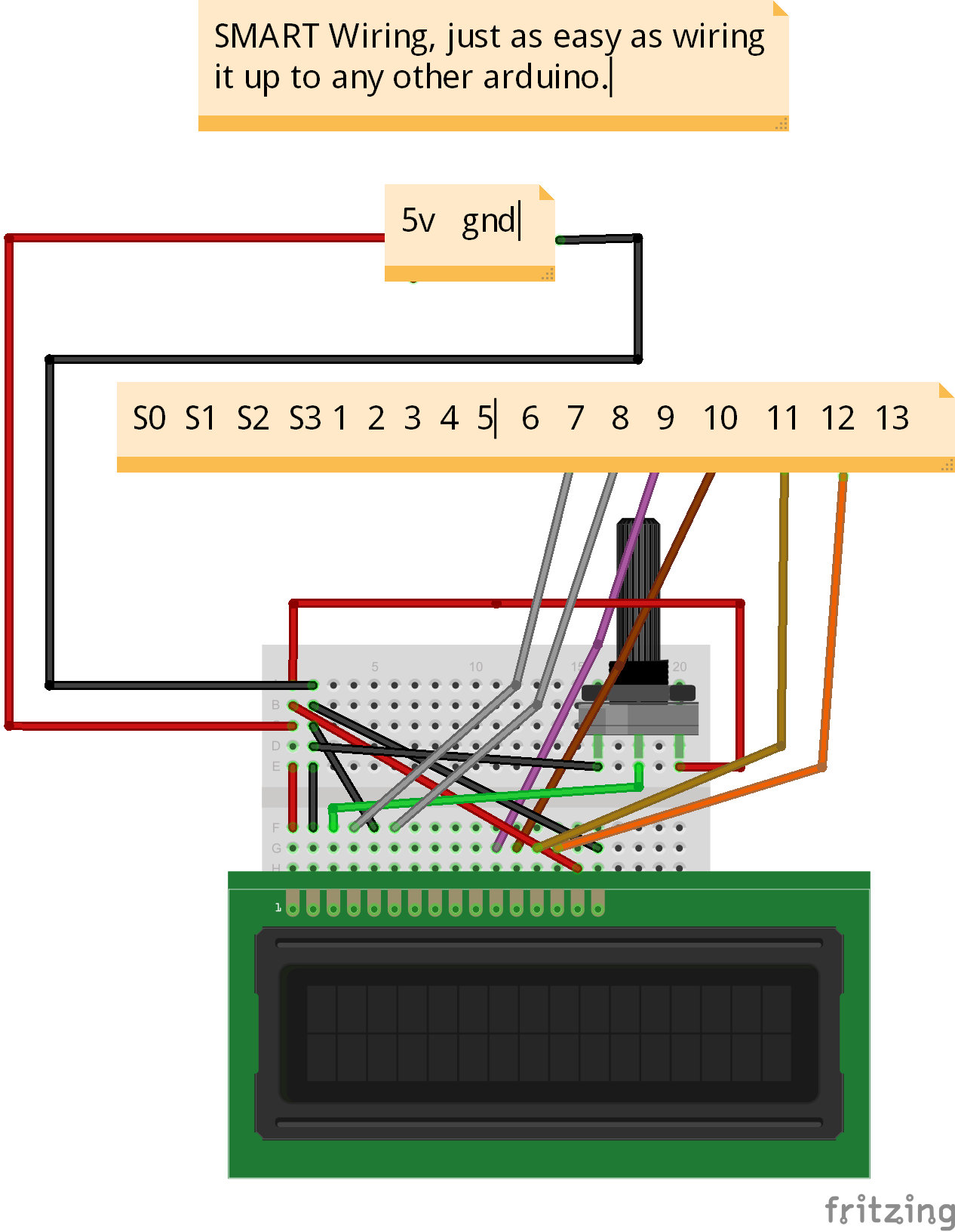
LinkIt Smart 7688 > LCD (On breadboard):
- 5v > 5v (Breadboard)
- Gnd > Gnd (Breadboard)
- (LCD) K > Gnd
- (LCD) A > 5v
- 12 > D7
- 11 > D6
- 10 > D5
- 9 > D4
- 8 > E
- (LCD) RW > Gnd
- 7 > RS
- (LCD) V0 > Pot. center pin (Left and right pins go to 5v and Gnd)
- VDD > 5v
- VSS > Gnd
Linkit ONE > Ultrasonic:
- Trig > D13
- Echo > 1K resistor > D12
- Gnd > Gnd
Linkit ONE > Potentiometer:
- A0 > center pin
- Gnd > right pin
Linkit ONE > Switch:
- 2 > Normally open
- Gnd > Signal
What's nice about this project is that you can have up to 250 LinkIt ONEs in your home and have every single one of them have multiple sensors, working simultaneously. You could also add location to each device, to see what switches are on in what rooms. Not too hard, since this whole tutorial gives you the base to hook up multiple sensors
The IoT cloud:
To make this project awesome, we want to see live view stats of your home. First you will need to sign up for carriots: https://www.carriots.com/ After creating an account make sure you log back in and press new device, here is some simple information that you'll want to fill out:
To start off lets create a simple sample where we will send a SMS to your phone as soon as an ultrasonic sensor is activated. Since it's easier for you to just follow images here you go:
Download the carriot API for python here, on the computer side, not the LinkIt Smart 7688, extract the zip and place everything in the carriot folder into a main folder called COM (The one under carriot-master, there is another one). Open up some text file and go back to cpanel.carriot.com, find the new device you created copy and paste that into the text file, like so "DEVICENAME@USERNAME.USERNAME." Then go to your account and find the API key that goes back to the smart device we created earlier. This is as simple as the IoT can get, the second we send a data stream using the carriot python API, carriot will text us that the "Ultrasonic sensor was activated." Since you do have to eventually pay for carriot, I will never use it, but this was just an example of how you can use a larger more expensive framework, when you can just do what I do and broadcast a nice looking webserver, that holds all that information.
The Code:
Now what do we want for our end result? Well we want to be able to update current information about the house, such as movements, lights and/or other things on carriot. So it's not going to be easy, at least not for me because this is the first IoT thing that used an actual API and not some local broadcast text file. For the LinkIt Smart 7688 to send data to the internet, guess what it actually has to be connected to the internet. At first I ran into this problem where I wasn't able to connect to connect to a wireless device and broadcast as one at the same time on the LinkIt Smart 7688. So I am going to go a little cheaty way where I use another client device that supports both to do the IoT handling for me. For this instance the laptop that supports Ethernet and Wireless... It's basically piping everything I receive on the LinkIt Smart 7688 to the laptop.
- Main Computer
To start off this process lets open up the folder with the python API (For carriots).
Here are all the files you will need in that folder to update carriot (look bellow for all code pieces, p.s. some is on github like the python carriot api).
- Top folder
- ---clicarriots
- ------__init__.py
- ------api.py
- ------client.py
- ---__init__.py
- ---setup.py
- ---porter.py
- VIEW-SENSORS.html
After placing all of the folders and files in the correct places, open the porter.py and modify the API-KEY and the DEVICE id where is needed, the rest will be handled for you. (Just remember this whole IoT thing is ported so the Linkit ONE will be slower because it'll have to create new threads to act as a server/client). Do the same thing for the VIEW-HSENSORS.html file (Open in notepad and replace where the capitalized "APIKEYHERE" with the Api Key found on the profile page of carriot, also changs "DEVICENAMEHERE" with the device name like this "SMART@username.username"
- LinkIt Smart 7688
This process is a lot simpler, open up WinSCP and place the Server.py code in the root folder, the same place where you placed the test file, here don't mess with anything unless, you want to add more sensors like a color sensor. I made it as plug and play as I could with the programming, besides the carriot part. Then you need to wire the LCD/Pot on it correctly, and use Arduino to flash the Server(Duo).ino code.
- Linkit ONE
Also pretty simple, for this one just make sure you wire up the sensors correctly which are located above, don't forget to flash this, double check the ONE code names Client.ino
Order of code:
For best results run these programs in this order (Make sure you have properly configured everything for your
- LinkIt ONE (Client.ino)
- LinkIt Smart 7688 (Server(Duo).ino)
- LinkIt Smart 7688 (Server.py)
- Computer (Porter.py) *Optional(It will be slower)*
- Computer(VIEW-SENSORS.html) *Optional(It will be slower)*
End result should be this:
I have said this multiple times, but just to be safe I want to say that especially with the potentiometer, that if you move it around too fast, then the carriot will have too much of a delay for the TCP sockets (Between the two devices) and make the python script on the LinkIt Smart 7688 crash, if it starts to lag, Ctrl+c one of them, preferably, the computer side, because I did a try catch that will still try to fix the LinkIt Smart 7688 side if that does happen. Once done the LinkIt Smart 7688 should say (On the LCD and PuTTy) that the Server has stopped responding
That's it if you have any question just contact me at smerkousdavid@gmail.com... Thanks for reading this much even, I spent a ton of time learning about the amazing new MediaTek LinkIt Smart 7688 Duo.


Comments