


Hardware components | ||||||
| × | 1 | ||||
| × | 1 | ||||
Software apps and online services | ||||||
 |
| |||||
| ||||||
After a bit of struggle I was able to wake up the watch. It was completely dead but when I removed the battery I could see with Raspberry debugger and load new firmware.
First thing I have found that it is possible to program it from Arduino.
Roger Clark has nice tutorials on how to get Arduino working, and there is a how-to get cheap USB programmer debugger: Arduino on BLE. I already had STM32F103C8T6 ARMSTM32 Minimum System Development Board from eBay so I decided to give it a try.
So I have now tried but I had problems with it I could not upload sample.
Debugger was installed:
It all seems OK:
Some suggested that I need to change the ID in registry, but I did not do that.
So I loaded Arduino sample with Raspberry watch just to check if I’m on the right track. And nRF accepted flash:
I did not have time to test it because it was Thursday and I need to rush to my Maker Space radiona.org.
I just surfed a bit and on some picture I saw that when programming with similar debugger they do not use SWD pins that are named on board, they have used pins A4 and A5, and that was bingo. I was now able to upload sample from Arduino.
But sample with Arduino did not work I was not able to get blink led on P0_07 (there is a vibration motor on that pin) so it should vibrate while HIGH.
I have searched how can I test if it is working and find The ARM® mbed™ IoT Device Platform so I decided to try it: https://developer.mbed.org/
I was really easy to start programming within MBED, I just selected some nordic board loaded and wrote a blink led and that worked. Button on pin P0_04 worked too.
OLEDNext was to get the OLED working. I have searched MBED libraries and found this one here: https://developer.mbed.org/users/synvox/code/SFE_MicroOLED/
I tested it and LCD woke up with only garbage on screen. Then I contacted the author of the library, Nenad, to help me with getting something on screen. Here is his response:
“Hello Goran, first you have to make sure, that your OLED SSD1306 controller is configured for the SPI interface. My adapted library only supports SPI, so it won’t work with OLEDs configured for I2C.
Secondly you will want to change the LCDWIDTH and LCDHEIGHT in SFE_MicroOLED.h to your actual OLED size. If it’s a 64 x 32 one, you have to set it to that. You can also try to change LCDCOLUMNOFFSET to a different value than 32. Normally on OLEDs with SSD1306 controller and less than 128 pixels width, the actual pixels are arranged in the middle of the SSD1306 memory width. So an OLED with 64 pixels width is often mapped with an offset of 32 in the controller memory. But it could be different for your particular OLED, so you could try an offset of 0 or any multiple of 8.
Third you should adapt the init sequence in SFE_MicroOLED.cpp to your OLEDs values. What i have seen from your attached datasheet, some values are different: command(SETMULTIPLEX, 0x2F) should be 1F instead of 2F (because your hight is 32 and not 48 pixels). command(SETCOMPINS, 0x12) should be 00 or 02 instead of 12. command(SETCONTRAST, 0x8F) per your datasheet is 4F and not 8F, but i doubt this will cause problems. command(SETPRECHARGE, 0xF1) per your datasheet is 1F and not F1. I’m not sure if this is important or maybe even a typo in the datasheet.
Best regards,
Nenad”
Datasheet of OLED is here: http://microco.sm/out/cEAZg
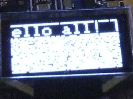
After some changes I was able to get Hello world on screen.
AccelerometerSo the next step to get really Smarty is to get the accelerometer to work.
First I have tried with library https://developer.mbed.org/components/KX022-1020-I2CSPI-3-axis-accelerometer/
But did not work, I ave tried I2C scanner to check if I use wrong I2C address but that did not work either. Then I read all pins that are connected to the accelerometer.
http://kionixfs.kionix.com/cn/datasheet/KX022-1020%20Specifications%20Rev4.0%20cn.pdf
//P0_16 SCL — default HIGH probably pull up //P0_15 SDO/ADR — default HIGH probably pull up //P0_14 SDI/SDA — default HIGH probably pull up //P0_13 Trigger — default LOW //P0_12 INT1 — default LOW //P0_11 INT2 — default HIGH probably pull up //P0_10 nCS — default HIGH probably pull up — from datasheet is this pin is high I2C is enabled so this is ok // The Slave Address associated with the KX022 is 0011111X, // where the programmable bit, X, is determined by the assignment of ADDR (pin 1) to GND or IO_Vdd. // So in this case we have adress 0011111 // 1Fh 3Fh 00111111
But nothing worked.
So I reported that to Roger, he pointed me to some I2C problems with nRF. Its possible the I2C scanner will not work, as I think it uses a bit of a trick. However I found this which links to this. So perhaps you could try that code, even if you have to use mbed.
I have tried, to get a response from the accelerometer and its address. It was using some wire library that is not compatible with I2C and I did not manage to easily get original KX022 library to work.
So I just tested register and got response, and then I decided to write line by line in main file and I got response from accelerometer X axis in MBED.
While I was working with MBED Roger worked in fixing Arduino to accept all pins, and change pinout that suits Smarty. He suggested that we open a chat room so others can join so I did so. Chat: https://gitter.im/nRF51822-Arduino-Mbed-smart-watch/Lobby
Roger created repository with Smarty pinout: https://github.com/rogerclarkmelbourne/Arduino_nrf51822
On my watch I broke pin 18 so now I use pin 17 as TX pin, you can change that in
ble-nrf51822-master\RBL_nRF51822\variants\Smartwatch\pins_arduino.h
It was easy to port some code from MBED to Arduino, so now we have all working as on MBED. OLED is still not working well. It still has some garbage on screen, accelerometer does not have library it is all in main .ino file. it does not use smart things like tap double tap flip interrupts. Accelerometer could wake up nRF to save battery life and so on.
I have pushed some samples on git you can check and fix within Smartwatch examples.
Join us in chat room, and on git, and thanks for reading :)
Ideas To Do- Flash old android phone (Samsung Galaxy Fame) to firmware that can do BLE — done on CM12.1 I can connect with bracelet
- Adding more sensors like pulse sensor or muscle sensor
- Epilepsy seizure detect
- On Threat CALL or send SMS
- Blind read SMS privately
- Troll other bracelets with Smarty bracelet
- One Bracelet to rule them all
Copyright © 2016 Lemilica.com


Comments