/* Motion Detector clock project built on face of an analog clock
*
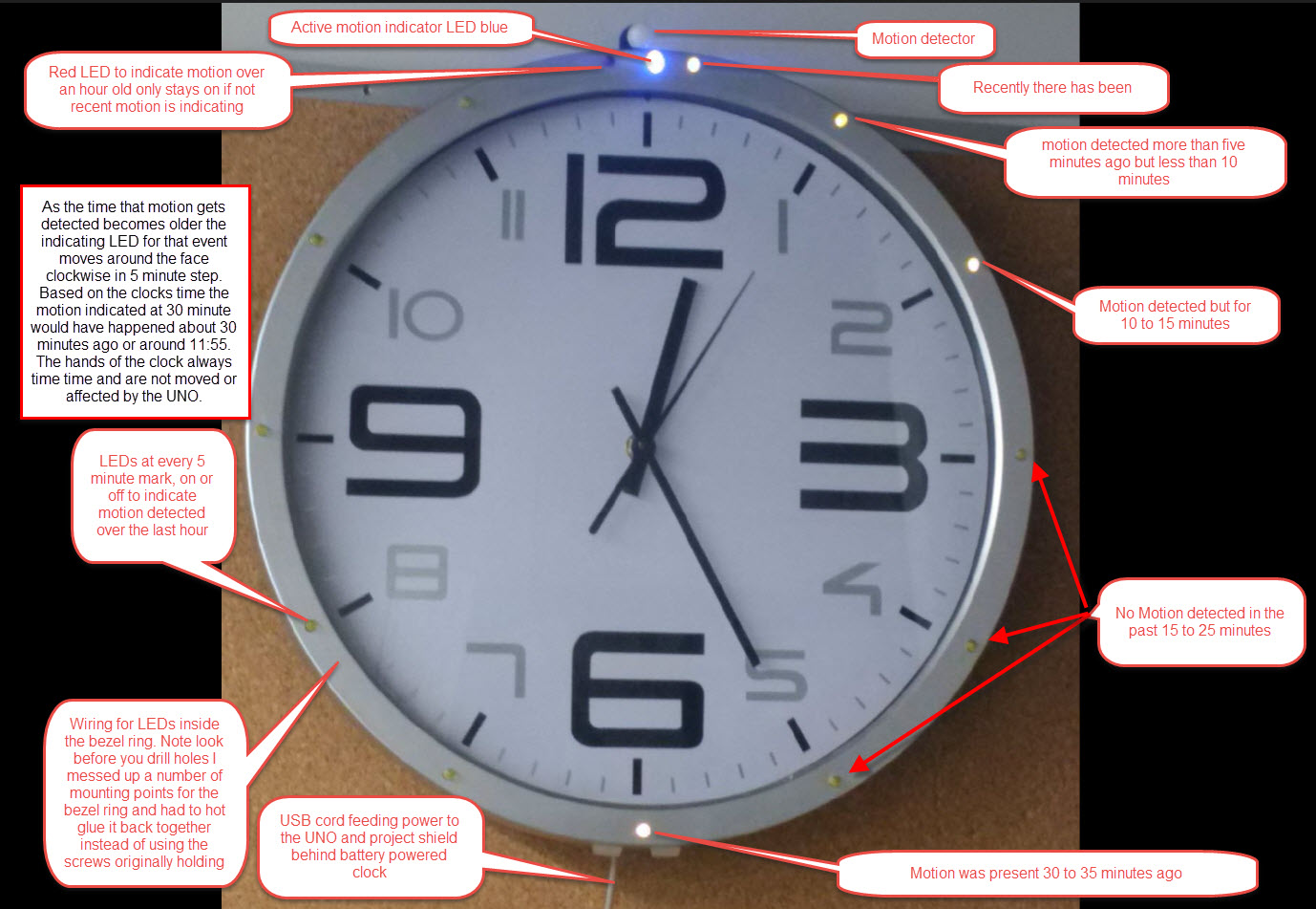
* The purpose is the keep track of how long ago there was motion in an area and
* display around the face of the clock in 5 minute intervals. For example
* A0 drives the LED at the five minute after the hour mark on the clock and
* A1 is driving the led at the 10 minute after the hour or 2 o'clock position
* Led's are power from the + 5 volt bus and the I/O ports are working as open
* collector current limited control points with 100 ohm resistors in series with each
* As each five minute interval passes the program moves data about the past 5 minutes
* around the face of the clock is a clockwise pattern
* for example if the led at 1 o'clock and 6 o'clock are on and the rest of the
* face leds are off that means motion was seenfive minutes ago and 30 minutes ago
* Five minutes later the same clock would have leds on at 2 and 7 O'clock points.
*
* it is great way to see if somebody has been sneaking into the kitchen for snacks before dinner
*
* after many changes I created this version using onboard UNO clock based timing using the millis function
* very fine acuraccy for a one hour duration no problem and no external timing needed.
* it has been striped to the bare bones so there is lots of room left to build in additions
* and there are still serial ports and one other interrupt free for use
*
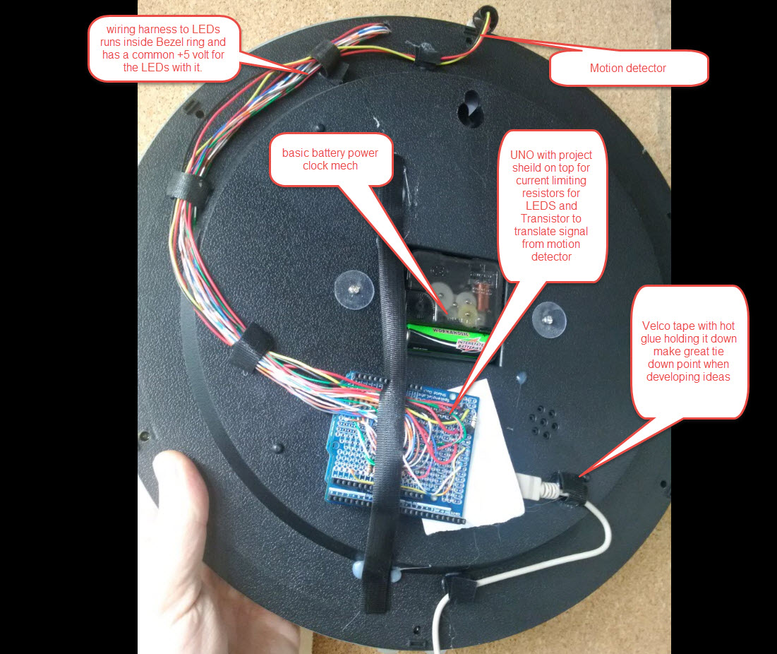
* A 2N2222 transistor is used to translate the IR sensor output to the
* interrupt input on pin 3 of the UNO. A 100K resistor is between the IR output
* and the base of the transistor. I also used the output of the transisitor collector
* to drive an LED directly above the 12 o'clock to indicate motion detected.
* the type of motion dectector I used was an EKMC1601113 PIR device
* But you could use a number of others include the contacts from standard
* alarm system motion detectors watch you don't connect to active 12 volts
*
* Things to do with this
* Add CharliePlexing for LEDS to save port space
* Add Blue Tooth or NFC to allow data to be collected
*
*/
// global variables build them first before running setup program.
// Important note setup array sizes bigger than what is needed to avoid
// mistakes of over writing array value in memory used for other things
// this can be very messy to track and fix, saves you a bunch of troubleshooting
long ACTC[20]; // Array to collect counts from the motion detector or Active Counter Timer Controlled
long DISO[20]; // Array to set status of each output display LED or Display Output yes this can be a smaller array value such as byte
unsigned long nowtime; // needed to allow time driven 5 min steps for display
unsigned long mytime; // Variables used to detect five minute intervals
unsigned long fivemin; // standard value for five minute detection period can be different if needed
void setup() { // set up IO ports IO 0 and 1 reserved for serial
// IO pins 2 and 3 reserved for use as interrupt inputs
// in this version only IO 3 gets used out of the four
pinMode(4, OUTPUT); // future spare port maybe an alarm relay output
pinMode(5, OUTPUT); // future spare port maybe an alarm tone output
pinMode(6, OUTPUT); // led for 35 minutes set high to turn off
pinMode(7, OUTPUT); // led for 40 minutes
pinMode(8, OUTPUT); // led for 45 minutes
pinMode(9, OUTPUT); // led for 50 minutes
pinMode(10, OUTPUT); // led for 55 minutes
pinMode(11, OUTPUT); // led for 60 minutes
pinMode(12, OUTPUT); // led for more than 60 minutes end of buffer
pinMode(13, OUTPUT); // spare port has led on UNO if indicator is needed
digitalWrite(4, HIGH); // not in use
digitalWrite(5, HIGH); // Used as output tied to IO2 as timer input
digitalWrite(6, HIGH); // led for 35 minutes set high to turn off
digitalWrite(7, HIGH); // led for 40 minutes
digitalWrite(8, HIGH); // led for 45 minutes
digitalWrite(9, HIGH); // led for 50 minutes
digitalWrite(10, HIGH); // led for 55 minutes
digitalWrite(11, HIGH); // led for 60 minutes
digitalWrite(12, HIGH); // led for 65 minutes ***
digitalWrite(13, HIGH); // not in use
pinMode(A0, OUTPUT); // led for 5 minutes
pinMode(A1, OUTPUT); // led for 10 minutes
pinMode(A2, OUTPUT); // led for 15 minutes
pinMode(A3, OUTPUT); // led for 20 minutes
pinMode(A4, OUTPUT); // led for 25 minutes
pinMode(A5, OUTPUT); // led for 30 minutes
digitalWrite(A0, HIGH); // Turn leds off by setting high output
digitalWrite(A1, HIGH); // set A1 high
digitalWrite(A2, HIGH); // set A2 high
digitalWrite(A3, HIGH); // set A3 high
digitalWrite(A4, HIGH); // set A4 high
digitalWrite(A5, HIGH); // set A5 high
fivemin = 300000; // this could be adjust to use different detection time windows and to fine tune for processor speed
mytime = millis() + fivemin;
pinMode(3, INPUT_PULLUP); // set port ot be an input with an internal pullup resistor
attachInterrupt(1, countmore, FALLING); // now turn pin 3 into an interrupt to collect motion detector pulses
clearactc(); // call subroutine to clear all data in counting array
cleardiso(); // call subroutine to clear all data in display status array
ledcontrol(); // call subroutine to update display output to latest state all off
// End of setup
}
void loop() { // main service routine
nowtime = millis(); // set time for this program cycle pass of the program make stable data instean of using ever changing value of millis
disotranslator(); // call subroutine to test data in counting array set the values in the display array
ledcontrol(); // call subroutine to run a cycle of setting the led display on or off
// really there is room here to run a lot of code or call other routines to do things
// the CPU is not very busy in this program and the motion is detected on a very
// brief interrupt. more code to set up the main loop.
// this next section detects five minute intervals and if true shuffles the data ahead one array position
// this bit of code replace the second timer interrupt routine saving two IO pins in the process
if ( nowtime > mytime ){ // test to see if five minute has passed yet
mytime = millis() + fivemin; // set next five munite interval
-- mytime; // correction factor for going via this branch once
shiftactc(); // calls subroutine to shift data array so leds status moves to 5 minuter older
} // end of updating actc array see you here again in five minutes
} // end of main loop start loop again and place if statement put you if fives has not passed
// SSSSSSSSSSSSSSSSSSSSSSSSSSSSSSSSSSSSSSSSSSSSSSSSSSSSSSSSSSSSSSSSSSSSSSSSSSSSSSSSSSSSSSSSS
// service subroutines
//
void clearactc() { // zero's data in all cells of ACTC array
for(int x = 0; x < 15; x++){ // create loop for counting array locations
ACTC[x]=0; // set cell to zero one at a time
} // next , left over from BASIC days just reminding you we go back to the FOR until loop is done
} // end of subroutine
void cleardiso() { // Clear display array to zero so no display output
for(int c = 0; c < 15; c++){ // creat count loop for cells of led display array data.
DISO[c] = 0; // set all array location to zero one at a time
} // next
} // end of subroutine
void disotranslator(){ // Check values in ACTC and makes display pattern to match data
for(int y = 0; y < 14 ; y++){ // create count loop for memory cell in arrays
(DISO[y] = 0); // clear any value out of old array loaction
if (ACTC[y] > 0) { // test count array value to see if more than one
DISO[y] = 1; // set led on if live data in count array
} // end of if
} // next
} // end of translator
void ledcontrol(){ // turns off all the Leds and then sets them ON according to their state in the DSIO array at this time
byte rp = 0; // set up local variables
byte rt = 0;
byte rz = 0;
byte ry = 0;
// Turn all Leds off with HIGH state
for (byte c = 0; c < 6; c++){ // set count loop for 2 leds in two groups
rp = c + 6; // create offset to address display leds
rt = c + A0; // create offset to address A ports yes you can address then as hex values
// this really drives some programmers crazy and lead to some dicussion in the forum
// if you are only going to run this on an UNO then use it
// for the purest of C go build yourself a table keep the world standardized
digitalWrite(rp, HIGH); // turns off the IO port LEDs used for second half of display
digitalWrite(rt, HIGH); // turns off the IO port LEDs used for second half of display
} // Next
// Turn on only the Leds that needs to be on
for(byte c = 0; c < 6; c++){ // set count loop for leds two groups of 6
rp = c + 6; // create offset to address display leds
rt = c + 7; // offset to pick display value from array
ry = c + 1; // offset to pick display value second half from array
rz = c + A0; // create offset to addres a port display leds
if ( DISO[rt] > 0){ digitalWrite(rp, LOW); } // tests display data array location for 0 or 1 and set led
if ( DISO[ry] > 0){ digitalWrite(rz, LOW); } // if greater than zero turn led port A0 on active low
} // Next
} // end of led control subroutine
void shiftactc() { // shift FIFO type array one to the right and clear cell zero (FIFO means first in first out refers to buffer or array operations)
int t = 0; // local variables defined
for(int x = 13; x > 0; x--){ // create loop that runs backwards 13 to zero
t = x + 1; // offset index
ACTC[t] = ACTC[x]; // move data right in FIFO
} // next
ACTC[1] = 0; // set first cell of array to zero
} // end of FIFO shift right function subroutine
// IIIIIIIIIIIIIIIIIIIIIIIIIIIIIIIIIIIIIIIIIIIIIIIIIIIIIIIIIIIIIIIIIIIIIIIIIIIIIIIIIIIIII
// Interrupt service routines
//
void countmore(){ // count motion detector input pulses on IO3 via Interrupt 1
ACTC[1] = ACTC[1] + 1; // increment count cell zero of array indicating count for motion.
// fastest interrupt service routine is best no fussing about here
}


_ztBMuBhMHo.jpg?auto=compress%2Cformat&w=48&h=48&fit=fill&bg=ffffff)


Comments