


This tutorial will teach you how to build a Wifi Smoke Alarm Notifier for about $10 dollars. You won’t have to code anything, and you won’t have to solder or buy expensive electronics equipment. Any services you are asked to use will be 100% free. Its that easy. Lets get started! Because most hackster's are pretty computer literate this tutorial is abbreviated, but you can read the full tutorial at www.simpleiothings.com.
I know you've seen these types of tutorials on the internet before, and usually they say something like, just buy a breadboard, soldering iron, breakout board, serial adapter, etc. etc. and after you've spent about $50 dollars you can build a cheap Internet of Things (IoT) device. Well, sorry internet. We nerds sometimes forget that most people don't really have these things lying around. That's why I built this tutorial around the idea that IoT devices can be built without coding knowledge, soldering, or complicated prototyping.
STEP 1: Gather Your Materials
Its a good idea to buy your parts first because on the sites where the merchandise is cheapest (Ebay or Aliexpress) shipping times are rather lengthy. Depending on where you live in the world, it might take some time for your components to reach you so its better to do this sooner in the process than later. A list of things needed for this project is provided below under the "Components" header.
STEP 2: Setup Your IFTTT Account & Recipes
The Wifi Smoke Alarm Notifier uses an internet service called If This Then That (IFTTT).
- Setup an IFTTT account
- Connect to the IFTTT Maker Channel.
- Sign up for the following recipes:
-
IFTTT Maker & SimpleIOThings Smartphone Notification Recipe
- Send your Phone an SMS
- Send a Friend/Family Member an SMS
- Call Your Phone
- Send an Email
- Download the IF App for your smartphone.
STEP 3: Install Firmware to your ESP8266 Dev Board
Download an appropriate ESP8266 Flasher from Github:
– 32-bit ESP8266 Flasher– 64-bit ESP8266 Flasher
Download NodeMCU Firmware for your ESP8266 Development Board from Github:
– NodeMCU Firmware for ESP8266 Development Board
Download LuaLoader from Github:
Connect your ESP8266 Dev Board to your computer like so. If you have Windows computer and an internet connection, the drivers for the board should automatically load. If for some reason it doesn’t you can Google “NodeMCU drivers” and a number of websites with appropriate files should show up.
Once your drivers are installed, you’ll also need to determine which communications port the device is connected to. Click your “Start” button and type “Device Manager.” Your device manager should pop up. Click and expand the “Ports (Com & LPT)” menu and you should see your device listed there. In my case, my ESP8266 dev board’s port was set to COM18. For now just take note of that and jot it down somewhere.
Now find your downloaded ESP8266 flasher program and start it. Change the port number to the port for your ESP8266 Development Board, which you jotted down earlier. Now click the Config tab, and click the topmost gear on the right hand side.
Once you click the gear icon, use the dialog box to find your NodeMCU firmware (.bin) file in your downloads folder and click "Open." Then go back to the "Operation" Tab and click "FLASH!" Once the progress bar moves all the way from left to right, your dev board can now understand the Lua language. Congrats!
Now open Lualoader.exe as an administrator. To open as an administrator, right click Lualoader.exe, and then click "Run as an Administrator." Once open, click Settings, Com Port Settings, and set the port to the one your dev board is connected to and click "OK."
Then click "Connect" in the menu bar of the Lualoader program. Your ESP8266 dev board should flash an LED for a second, and your Lualoader will show you some strange characters. Congrats, you now have a dev board that is ready to receive a program.
STEP 4: Install Sensor Specific Software to your Dev Board
Download Sensor Software - Great! Now your dev board speaks Lua. Its ready to start communicating with the world. Just visit the SimpleIOThings Downloads Page and download the Sensor Software in the file SimpleIOThings.zip.
Configure Your ".lua" Files - Before you upload the files to your dev board, run the SensorSetup.bat file. It will take you through a number of prompts that will configure your Smoke Alarm Sensor with your IFTTT Maker Key, as well as sensor input thresholds. There are recommended values for a Smoke Alarm Sensor so enter those values unless you understand the variables involved and want it to perform another way. There may be some prompts that ask you flash your dev board, but ignore those since you've already done that.
Upload Files To Your Dev Board - Now go into your Lualoader and click "Upload File..." on the right side menu. Find your unpacked folder and click on any .lua file and click "Open." Your first .lua program file will upload into the dev board. Now that you've set the right directory, click the dropdown menu and click "< Upload all .lua files." Now ALL of your .lua program files will upload into your dev board.
Setup Wifi On Your Dev Board - One last thing. Before we hit restart, setup your wifi network name and password. To do that, enter the wifi network name and password for the network the Smart Button will use and click "Set AP."
Now click "Restart!" If everything went well, you should see "Listening for Sensor Inputs..."
STEP 5: Build the Smoke Alarm Notifier
All the way back in step 1, we talked about gathering materials. Hopefully now you have everything in hand and your board is programmed. Go ahead and get all your materials together in one space.
Connecting the Wires
Go ahead and unplug your dev board.
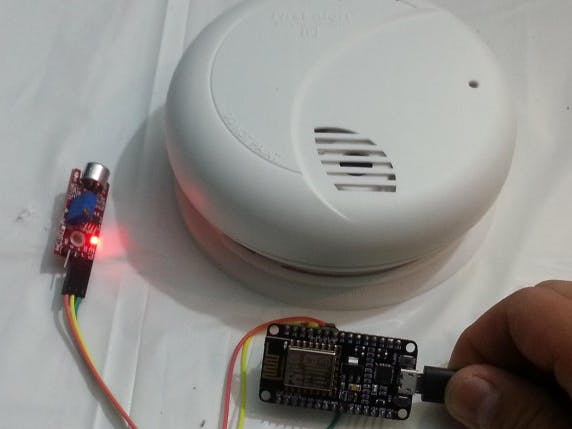
Now, grab the microphone sensor and three female jumper wires. Plug the jumper wires into the "D0," "GND," and "+" pins of the sensor.
Now grab your dev board, and observe the names of the pins on the board. Go ahead and plug your jumper wires into the "GND", "3V3", and "D2" pins on the right hand side, making sure that "GND" connects to "GND", "+" connects to "3V3", and "D0" connects to "D2."
Calibrating Your Microphone Sensor (First Time)
Now that the cables are all connected, go ahead and power your dev board with a microusb cable and place the sensor near your smoke alarm. If everything was connected properly, at least one light should be illuminated on your sound sensor. You'll notice that the sensor has a small screw on it. Turning this screw calibrates something known as the "potentiometer." In simpler terms, this screw determines what level of sound will trigger a signal through the "D0" pin from the sensor to the dev board. If you turn the screw clockwise, a lower level of noise (quieter) will cause the sensor to send a signal to the ESP8266 Development Board. If you turn the screw counter-clockwise, louder noises are required to trigger a signal to the development board. You can also visually confirm when your sensor is sending a digital signal to the dev board because a second LED light will illuminate on the board. Use the 2nd LED and the screw to set the potentiometer to a level where normal ambient noise and conversation will not trigger a signal to the dev board (i.e. 2nd LED does not light up).
Now go ahead and test your smoke alarm (most smoke alarms feature a "test" button which will trigger a limited number of alarms. (Note: The alarm will be loud. If you're sensitive to noise, it might be a good idea to wear hearing protection). The 2nd LED should light up when the alarm is ringing. Now turn the screw counter-clockwise until the 2nd LED does not light up when the alarm is ringing. Once you get there, stop, then turn the screw clockwise until the 2nd LED is just lighting up again. Stop turning the screw and keep this configuration until later.
Modifying Your Enclosure
Okay, now lets move onto the enclosure. Actually, the enclosure is nice to have, but not 100% necessary. You could put this project inside of a soap case or a pencil box, or other common household objects. Just make sure the case is not flammable, and isn't conductive (i.e. not metal). At about a dollar though, I think its nice to have a professional looking enclosure, so I think its worth buying one. The enclosure needs a place for wires to come out of the back, and for sound to enter through the front. I sawed a piece of the back of the enclosure out, and used pliers to tear off some of the enclosure so sound could enter through the front. Here's some pictures of how I modded my enclosure.
The way I did it with a saw is kind of "hacky" (pun intended) but worked for me. Alright, now you can put your electronics into the enclosure. Plug your usb cable into the dev board, and make sure your jumper wires are well positioned, but don't close the project box just yet.
Calibrating Your Microphone Sensor (Second Time)
Now that your sensor is inside the enclosure, you will need to set your microphone sensor to be triggered by lower sound levels (since the enclosure will dampen some of the Smoke Alarm noise). Turn the screw by a half clockwise turn, then close the project box. Orient it towards the smoke alarm similar to how it will be oriented when finally installed, then and test the alarm. If its possible, try to observe if the 2nd LED is triggered. If that's not possible, connect the device to your PC, and use LuaLoader's readout. By now, the software you've uploaded should be working and displaying "sensor input counted" if the smoke alarm is triggering a signal.
If its not sending a signal to the dev board, turn the screw clockwise by another half turn, close the project box, and read again. Repeat this process until the smoke alarm triggers a signal while inside the enclosure.
Step 6: Final Installation
The last thing you'll want to make sure is that the Wifi Smoke Alarm Notifier works once its installed on a wall or ceiling near your Smoke Alarm. I used some push pins to make sure both the enclosure and the cord are secure, and look neat. Of course, I tested it again once it was up on the wall, and it's been there ever since, vigilantly waiting 24/7 for an alarm to sound.
I hope you enjoyed building a super simple Internet-of-Things device. Hopefully you will be able to use it for something useful, or use it to do something fun. If you enjoyed this tutorial, go to simpleiothings.com and check out some other cool projects. Follow us on Twitter (@simpleiothings) and Facebook to get notified when new posts and projects are published. Thanks for reading!


Comments