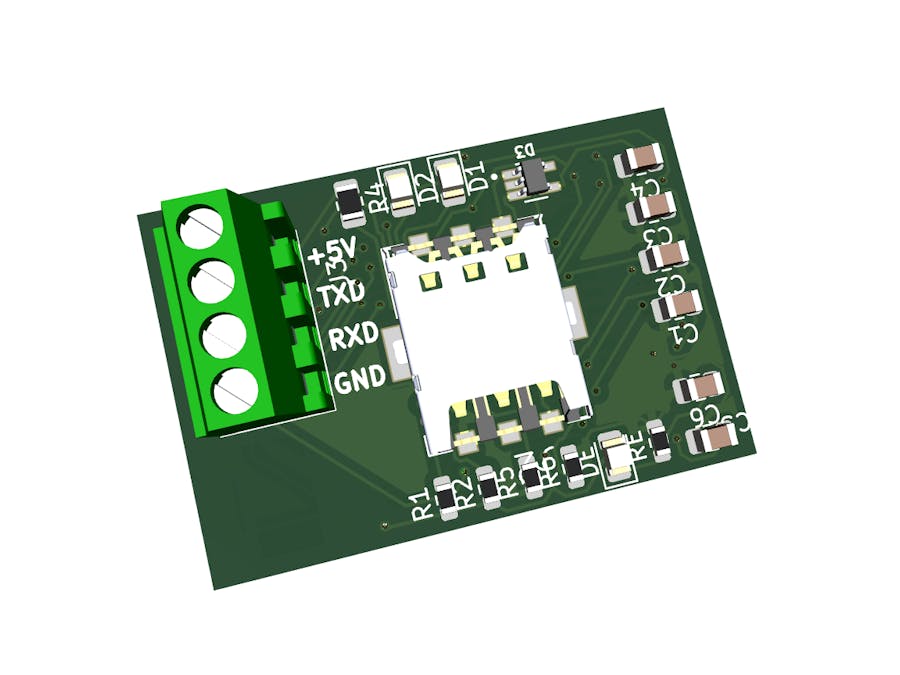
This project demonstrates how you can develop various GPS/ GPRS and SMS capability developments via the SIM800 integrated circuit. It introduces an electronic board that can connect with a microcontroller such as Atmega 328p, STM32, and ESP32, giving it the most required GPRS, GPS, and SMS data transmission and location tracking functionalities.
IntroductionHave you ever wondered how you locate the exact location of anything globally and get real-time information about the item under investigation? Worry no more; we will make that possible for you in this project. We are going to build a simple board based on the SIM800 IC that will have the ability to transmit necessary coordinate data in the form of links and SMS to your preferred viewing devices, such as mobile phones. For the board to work, it will be incorporated into other development boards such as the Arduino, ESP32, and STM32 boards. Through this project, which is suitable for the public transport sector, the vehicle's owner will be able to know the exact location of the car through continuous tracking via Google Maps links transmitted by the board into their phones. This section of the project deals with hardware development and how you can order the manufacturing of the same hardware through our preferred fab house.
Requirement for the projectFor the success of the project, the following electronic components are required.
- 100nF Unpolarized capacitor, small symbol C1, C3 C_0805_2012Metric
- 1nF Unpolarized capacitor, small symbol C2 C_0805_2012Metric
- 10nF Unpolarized capacitor, small symbol C4 C_0805_2012Metric
- 470pF Unpolarized capacitor, small symbol C5 C_0805_2012Metric
- Unpolarized capacitor, small symbol C6 C_0805_2012Metric
- Red LED Light emitting diode, small symbol, filled shape D1, D2, D4 LED_0805_2012Metric
- ESDA6V1W5 D3 SOT65P210X110-5N
- U.FL-R-SMT-1_10_ J1 HRS_U.FL-R-SMT-1_10_
- SIM8051-6-0-14-00-X-REVD J2 GCT_SIM8051-6-0-14-00-X-REVD
- Conn_01x04 Generic connector, single row, 01x04, script generated (kicad-library-utils/schlub/autogen/connector/) J3 TE_282834-4
- BC817 0.8A Ic, 45V Vce, NPN Transistor, SOT-23 Q1, Q2, Q3 SOT-23
- 470 Resistor, small US symbol R1, R2 R_0603_1608Metric
- 4k7 Resistor, small US symbol R3 R_0402_1005Metric
- 10k Resistor, small US symbol R4 R_0805_2012Metric
- 47K Resistor, small US symbol R5, R6 R_0603_1608Metric
- 26.1 Resistor, small US symbol R7, R9, R10 R_0402_1005Metric
- 0 Resistor, small US symbol R8 R_0402_1005Metric
- 2k7 Resistor, small US symbol R11 R_0603_1608Metric
- 100nF Unpolarized capacitor, small symbol C1, C4 C_0805_2012Metric
- 1nF Unpolarized capacitor, small symbol C2 C_0805_2012Metric
The circuit is designed using KiCAD while considering various component datasheets. Below is the electronic circuit for the project.
First, remember that we intend to build a module with GSM ability. This means the board can connect to mobile phone networks, send or receive calls and SMSs, and connect to the Internet through IP, GPRS, or TCP. This board has to be powered by an input of 5V DC regulated to 4.2V DC, meaning that the module can be powered using the 5V output pin of the microcontroller or the laptop RJ45 port using USB.
The module's RX and TX transceiver pins connect to the microcontroller, allowing them to communicate. We can program the module to achieve the desired functionality by interconnecting with a microcontroller.
PCB LayoutThe PCB layout is done via KiCAD. The board is interconnected per the schematic above, and all traces are drawn per the standard.
- This module is suitable for use in the areas of:
- Home automation
- Emergency systems
- Remote sensing
- Communication
After generating all the manufacturing files, I moved to the PCBway home page to order for the manufacturing through the online instant quote page. Here, I started by inputting the size of the board, selecting the material and quantity of the boards, and selecting the layers of my board.
Click calculate to get the first quote, then hit save to cart. Then, another window will pop out where you need to submit your Gerber files for the team of experts to review and give you a final quote.
Upload the Gerber file, submit it, and wait for the quote to be completed. Make payment as required through various available payment methods and wait for the order to be delivered in seven days.


_4YUDWziWQ8.png?auto=compress%2Cformat&w=48&h=48&fit=fill&bg=ffffff)


_Ujn5WoVOOu.png?auto=compress%2Cformat&w=40&h=40&fit=fillmax&bg=fff&dpr=2)

Comments