

Hardware components | ||||||
_ztBMuBhMHo.jpg?auto=compress%2Cformat&w=48&h=48&fit=fill&bg=ffffff) |
| × | 1 | |||
 |
| × | 1 | |||
| × | 1 | ||||
| × | 1 | ||||
Software apps and online services | ||||||
| ||||||
 |
| |||||
| ||||||
Back in July of this year a few design students from Germany launched a satirical Kickstarter to prototype the Fridgeye; a beautiful light sensor for your refrigerator. Combine the fact that we generally expect ludicrous hardware projects to appear on Kickstarter with how much effort the team put into making it seem real, it's no wonder that people weren't sure what to think. It's no secret that I was a fan of the project from the beginning but not because I'm dying to know what my fridge light is doing. The Fridgeye is a perfectly scoped project to tackle with potential for growth if you're looking to get started in the Internet of Things.
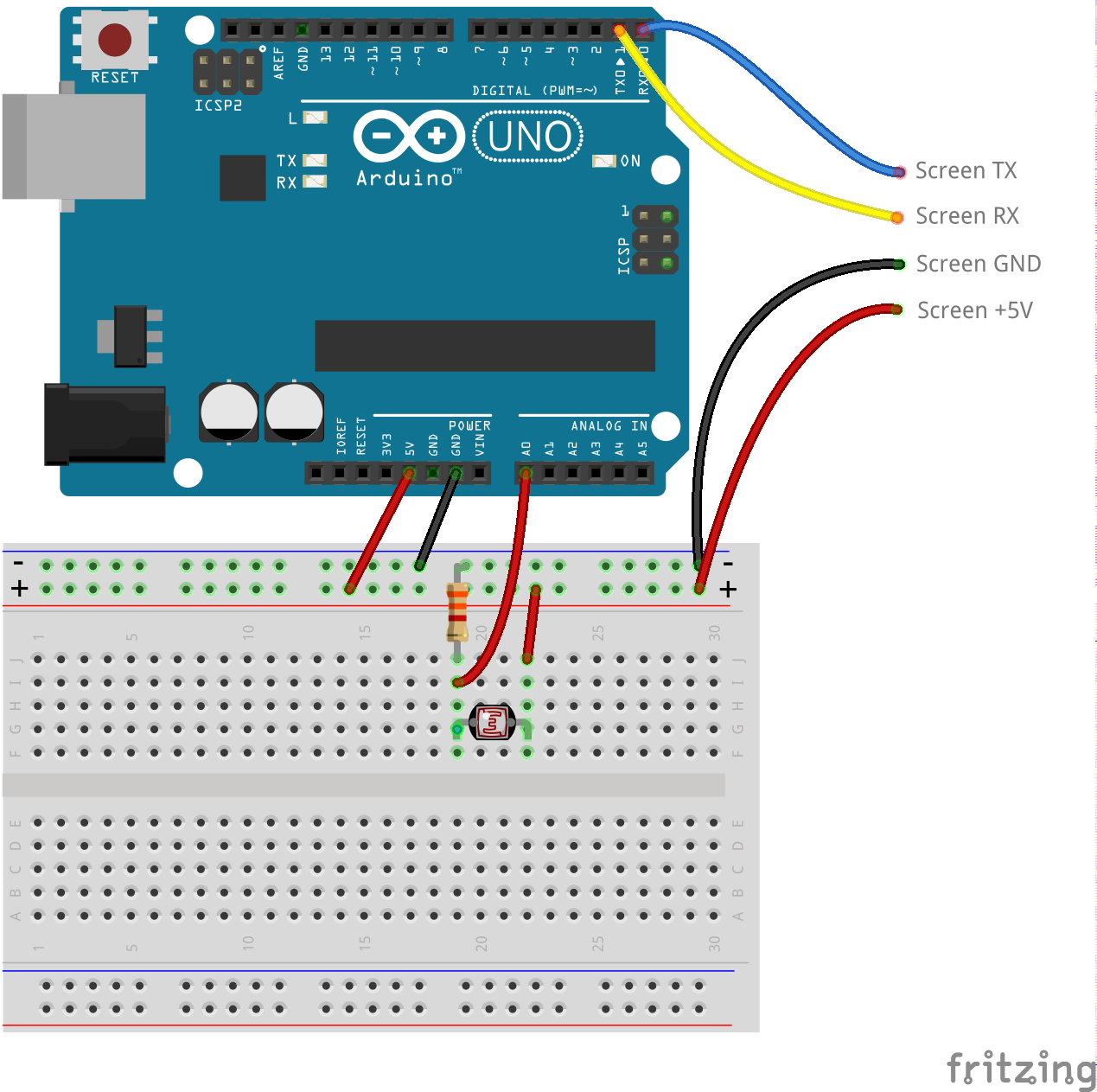
Build The Fridgeye DeviceThe bulk of this post will be focused on getting the Fridgeye app running with the Nextion touch display connected to an Arduino but before we get that far we need an actual device that can sense light. No problem. Let's take 5 minutes and build one. I promise it won't take a second longer. All you need is an Arduino, breadboard, photoresistor, and a 3.3K resistor. We'll wire it up like this. Don't worry about the screen connections just yet. Just focus on the Arduino, resistor, and photoresistor.
I actually had a ProtoShield lying around; so I slapped a mini breadboard onto it so that I could keep everything in one nice shield-stacked package but still have the freedom of a breadboard. This is what mine looks like.
Okay, I lied, that only took about 4 minutes. But you can use the minute you have left to throw down this super simple sketch on your Arduino and watch the serial output of the light sensor from within the Arduino IDE.
void setup() {
 Serial.begin(9600);
}
void loop() {
 int val = analogRead(A0);
 Serial.println(val);
 delay(500);
}
After you program the Arduino open the Serial Monitor from the Tools menu. Make sure the baud rate is set to 9600. You should see a new integer value representing the light level about every half second. Go ahead, take a minute and play around with it. Cover the sensor up, turn the lights on and off, and maybe even try shining your smartphone flashlight on it. Watch the values change. You'll notice they range from almost 0 in complete darkness to almost 1024 when bombarded with light.
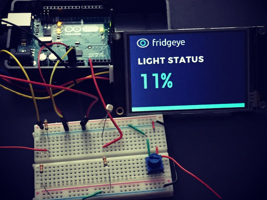
What's the Fridgeye App?The Fridgeye app is the trusty companion to your Fridgeye device. Gone are the days when devices went stag. Everyone knows that in today's grand world of IoT your device doesn't stand a chance unless it has an app of some sort to go with it. It's peanut butter and jelly, milk and cereal, peas and carrots.
The app is quite simple. If we take a look at the Kickstarter page, it's literally just the percentage of light that the Fridgeye detects and appears to only ever be 0 or 100 percent.
I'm sure we can do a little better and use some of those 99 values in between so they don't feel bad. Let's go straight from the concept drawings and bring it into the real world.
Getting Started with the Nextion DisplayFor this project I'm using the Nextion Enhanced 3.5" touch display. It's a full resistive touch screen display that's meant to handle the heavy lifting of graphic control so that even very low end devices like the Arduino can talk to it over a pair of serial lines. While the display itself is very nice the documentation can be very hard to navigate, especially for beginners so let's walk through it one step at a time.
Display Programming Model
If you've ever programmed an Arduino to use a display before you've probably used something like a simple graphics library that abstracted away the low level commands of drawing on the screen surface. While very nice, those libraries still require you to do a lot of the pixel pushing to draw things on the screen. The Nextion displays use a different approach that will feel very familiar if you're used to the MVVM or MVC patterns. Essentially, the app appearance is configured entirely up front and stored on the screen itself. At runtime the Arduino references pieces of the UI using pre-assigned IDs. The Arduino also gets information back from the screen like touch events in the same manner. That means that instead of drawing things at runtime, the Arduino is only acting as the conductor of the the views and controls. If that doesn't make sense just hold on with me a little longer as we step through it.
Prepare the View
Because our Fridgeye app is so simple, it will only require a single page. The Nextion display, however, is capable of handling very complex applications with multiple pages and transitions. Whether you are designing a simple app like ours or a very complex one you will use the Nextion GUI Editor. It's a WYSIWYG editor for the Nextion family of displays and will help us get our layout just right. Again, the documentation and getting started experience can be very challenging for beginners but once you get the hang of it you'll be designing complex layouts quickly.
Before we crack open the editor, we need to prepare a background asset. Referencing our mock image above we can see that the only thing that will change on our display at runtime is the percentage of light detected. The logo, background color, and green bar at the bottom are static. Let's make an image with those items that we can use as our background. This took me all of 5 minutes in GIMP and looks like this.
The important thing to remember here is to make the image exactly the size you need for your screen. In my case, I'm using the 3.5" screen which translates to 480 x 320 pixels. That's exactly how big I made my image in GIMP.
Using the Nextion EditorNOTE: The Nextion Editor requires the .NET Framework and is currently supported only on Windows. I was able to run it without any problems in a Windows 10 Virtual Machine through Parallels on my Macbook. I did not test it in Wine on Linux.
The following steps will walk you through creating our simple app layout in the Nextion Editor. With the Nextion Editor open perform the following steps.
1. File->New. Give your project a name and location on your machine.
2. A dialog will pop up asking you to select your device. In my case I selected Enhanced and the 3.5" model number. DON'T CLICK OK. Continue to step 3.
3. Click on the DISPLAY tab in the upper left-hand corner of the dialog. Select the 90 Horizontal display direction.
4. Now you can click OK.
5. Click Picture from the Toolbox on the left. This will add an element p0 to your outline.
6. In the Picture/Font pane in the bottom left make sure you have the Picture tab selected.
7. Click the + symbol.
8. Navigate to the image we created in GIMP that provides the background for our app and click Open.
9. In the attribute pane on the right double-click in the pic attribute value area. A picture selection dialog will open with our app background.
10. Select the app background and click OK.
11. Click Text from the Toolbox. This will add a text area named t0 in the upper left-hand corner of our display. Note the value of the id attribute as you will need it later when programming the Arduino.
12. Drag the text area to the desired location below the words "Light Status" and resize it so it fills a large area.
13. To fix the white background we need to set the text area background to be a cropped version of our main background. With t0 selected change the sta attribute within the attribute pane from solid color to crop image.
14. Double click the picc attribute value for the text area t0. This will open the picture selection dialog. Select the main background image again and click OK. This has the effect of making the text area background transparent.
15. Change the pco attribute of t0 to be whatever font color you want. I went with a custom color of Red: 125, Green: 231, Blue: 191.
16. From the Tools menu select Font Generator.
17. In the Font Creator dialog select a height of 96 and select whatever font you would like to use. Mine is Montserrat.
18. Give the font a name and click Generate Font. Be sure to save it in a location that is easy to remember. We'll need it again in a sec.
19. Close the Font Creator dialog. You will be asked if you want to add the generated font. Click Yes. That font is now referenced as font index 0.
20. Add some dummy text to t0 to see what it will look like by changing the txt attribute of t0 to 100%. You have to click out of the attribute value area for the editor area to update.
21. Reposition t0 to your liking.
22. Click Compile in the top toolbar.
If all has gone well you will now have a compiled TFT file ready for use located in %AppData%\Nextion Editor\bianyi.
Update the DisplayThere are a couple of ways to get our fancy new design onto the display itself. If you have a USB-to-TTL converter you can connect directly to your screen from within the Nextion IDE and upload the compiled TFT file directly. Otherwise you will need to copy the compiled TFT file to a micro SD card which can be inserted directly into a slot on the back of the screen. The SD card MUST be FAT32 formatted and must have a single TFT file on it or you will run into errors. The Nextion Editor puts successfully compiled files in the following directory on Windows.
C:\Users\[your username]\AppData\Roaming\Nextion IDE\bianyi\[project name].tft
Note, you may have to enable viewing hidden files as the AppData folder is marked as hidden.
With the TFT file on the SD card perform the following steps.
- Ensure the display is powered off
- Insert the SD card into the display
- Power on the display. The screen will show that it is updating.
- Once the update finishes power off the display
- Remove the SD card. Don't forget this step as the screen will not run your view with the SD card still inserted.
- Power on the display again. You should now see our beautiful Fridgeye app. The only thing missing is the value from the light sensor.
Now that the display has our app view on it we need to write some code on the Arduino so that it can interact with it and set the light status percentage.
Install the Nextion Library
1. Download the latest version of the Nextion Arduino library.
2. Copy the entire ITEADLIB_Arduino_Nextion
folder to your Arduino libraries folder. On Windows it will be located at:
C:\Users\[your_username]\Documents\Arduino\libraries
On Mac it will be located at:
~/Documents/Arduino/libraries
3. If you are using an Arduino Mega skip to step 7.
4. If using an Arduino Uno open the NexConfig.h
file located in the ITEADLIB_Arduino_Nextion
folder that you just copied into the Arduino libraries folder.
5. Comment out the following lines:
#define DEBUG_SERIAL_ENABLE
#define dbSerial Serial
6. Change the #define
for nexSerial
to be Serial instead of Serial2. This allows us to connect the display directly to the RX and TX lines on the UNO.
#define nexSerial Serial
7. Restart the Arduino IDE if it was already open. This will cause the library to be available via the menus.
8. From the File menu select New to create a new sketch.
9. Replace the default sketch code with the following:
#include "Nextion.h"
long lastUpdate;
int SENSOR = A0;
NexText t0 = NexText(0, 2, "t0");
void checkSensor()
{
   int val = map(analogRead(SENSOR), 0, 1024, 0, 100);
   String displayText = String(val) + "%";
   t0.setText(displayText.c_str());
}
void setup(void)
{
   lastUpdate = millis();
   pinMode(SENSOR, INPUT);
   nexInit();
}
void loop(void)
{
   nexLoop(NULL);
   if (millis() - lastUpdate > 100)
   {
     checkSensor();
     lastUpdate = millis();
   }
}
If your Arduino foo allows you to understand that sketch then you can skip this section entirely. You're awesome. If you're new to Arduino code don't let this scare you. Let's take a look at this sketch piece by piece.
#include "Nextion.h"
This indicates our intention to use the Nextion library. We don't need to do anything else as the Arduino IDE knows where to find it since we put it in the libraries folder.
long lastUpdate;
This is simply a variable named lastUpdate that will allow us to control how often we update the screen later on in the sketch.
int SENSOR = A0;
Here we are just giving the A0 pin on our Arduino a more code-readable name that we can use to reference it later. This doesn't really matter in this sketch as it's the only I/O pin we are dealing with but it's a good habit to be in as it will come in handy when you have lots of things connected to your Arduino.
NexText t0 = NexText(0, 2, "t0");
Here we are creating an object in our sketch that refers to the text element we created in the GUI. Remember that we named it "t0
". The first argument is the page number which is 0 in our case and the second argument is the component ID which we recall from earlier is 2. If you forgot to write it down just go back into the Nextion Editor, click on the t0 element and look in the attribute pane to see the ID.
void checkSensor()
{
   int val = map(analogRead(SENSOR), 0, 1024, 0, 100);
   String displayText = String(val) + "%";
   t0.setText(displayText.c_str());
}
The checkSensor() is the meat of our app. On the first line we are actually performing two operations. First we call analogRead(SENSOR) which gives us an integer value representing the voltage present on pin A0 (remember we called it SENSOR). On an Arduino UNO the analogRead call will return a value from 0 to 1024 but we want to map that into the range of 0 to 100 percent. No problem. The Arduino IDE has us covered with a built-in map() function which allows us to specify a value followed by a [from range] and [to range]. We then change that int value to a String type and tack on a % sign. The last step is to call setText() on our NexText t0 object we created earlier.
void setup(void)
{
   lastUpdate = millis();
   pinMode(SENSOR, INPUT);
   nexInit();
}
This is the standard Arduino setup function that gets executed before any other sketch code. We initialize lastUpdate to right now by calling the millis() function, setup our A0 pin to be an input and initialize the Nextion library.
void loop(void)
{
   nexLoop(NULL);
   if (millis() - lastUpdate > 100)
   {
     checkSensor();
     lastUpdate = millis();
   }
}
In Arduino programming the loop() function is continuously executed until the Arduino is powered off and back on or reset in some other way. We have to continually service the Nextion library by calling nexLoop(). The NULL parameter just means that in our example we aren't listening for any touch events from the screen. We then have a very simple check to see if it has been more than 100 milliseconds since our last sensor reading. If so we call our checkSensor() method and set the lastUpdate variable to right now with another call to millis().
That's it. Less than 30 lines of code is all it takes to interact with our Nextion display from an Arduino.
Connect the DisplayBefore we actually connect the display to our Arduino let's go ahead and push our sketch code to it from the IDE by clicking on the little right arrow in the top bar or by using the shortcut Ctrl+U.
The screen can't be connected during upload because on the Arduino UNO the same serial lines the display uses are needed by the IDE to push new sketches. If you are using an Arduino Mega instead you don't need to worry about that.
Now with the code pushed to the Arduino let's connect the display. Don't forget to remove power from the Arduino first. See the Fritzing diagram for connection information.
When you power the Arduino back up your Fridgeye app should be happily showing you the current light sensor reading.
Wrapping UpWhew! We made it. So, you might be asking at this point with a hint of rage in your tone "WHAT GOOD IS THIS? I have to put the entire thing in my fridge so I won't even be able to see the screen." You are a very astute pupil but I never said any of this was useful, just a lot of fun to build and learn.
If it makes you feel better though I challenge you to take this project a step further and figure out how you could put the sensor in your fridge and have the display somewhere else. There are so many ways to accomplish that goal. WiFi, Bluetooth, Zigbee, and generic radio transmitters are just a few that come to mind. Lots of options and lots of things to learn. If you do try your hand at it please reach out to me on Twitter @KevinSidwar or send me an email (Kevin at sidwar dot com). I'd love to hear about your adventures in IoT. Until next time, happy hacking.
If you enjoyed my post and would like to learn more about getting started in IoT then you might be interested in a course I'm currently creating around the Fridgeye concept. If not, I truly thank you for actually reading all the way to the end. Hope you have an awesome day. You deserve it.


Comments