I wanted to design a simple RGB control to use with 12v "dumb" RGB LED strips available cheaply from various shops. they have 4 pins; a +12V common, 3 GND pins for 3 colors. as it's obvious, they are common anode.
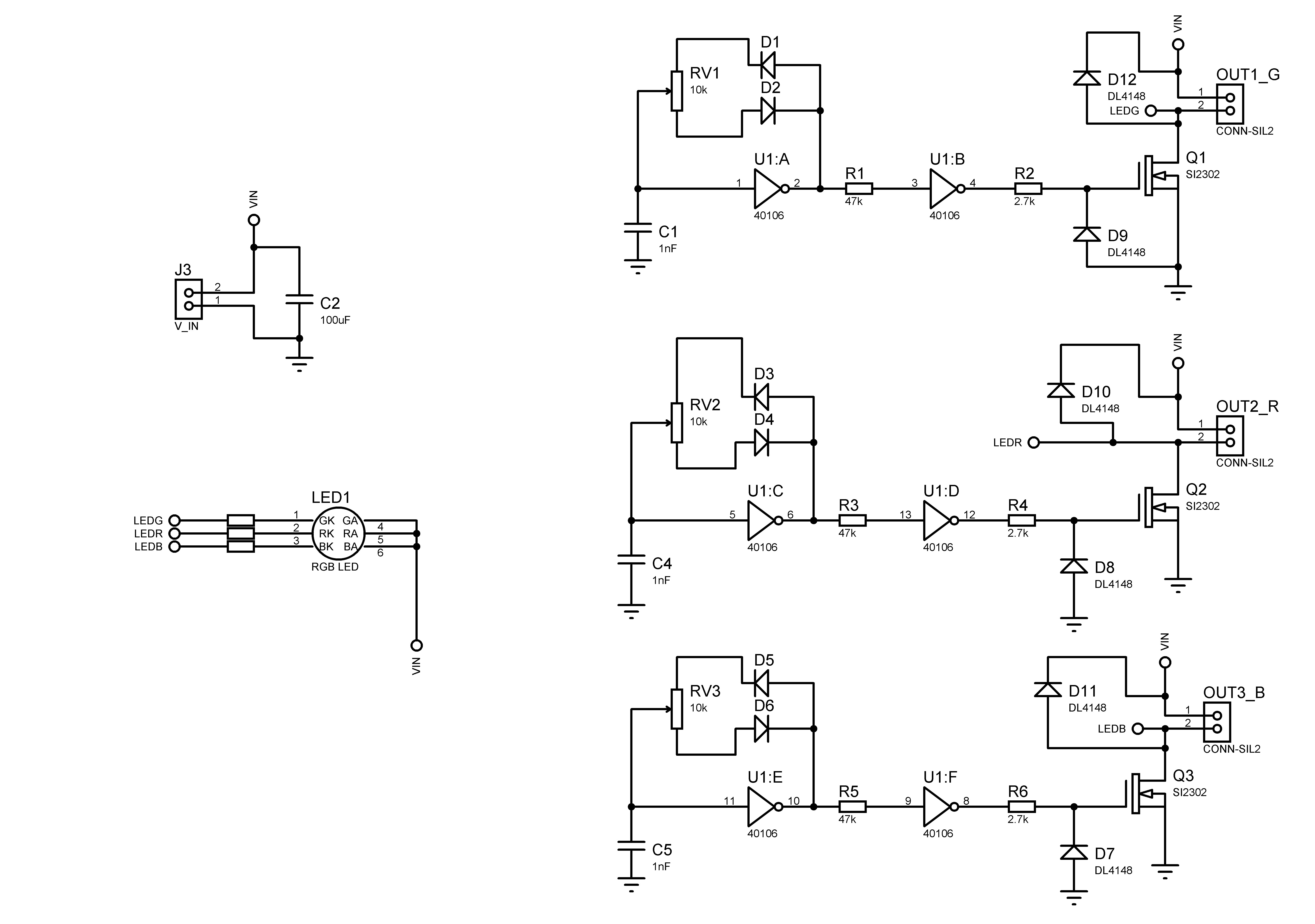
The color pins are driven with 3 n-chanel power MOSFETs. the PWM signal is generated using NOT gates of a CD40106 (HEF40106) IC. it's a common CMOS gate IC available everywhere. some other cosmetics are added for better usability.
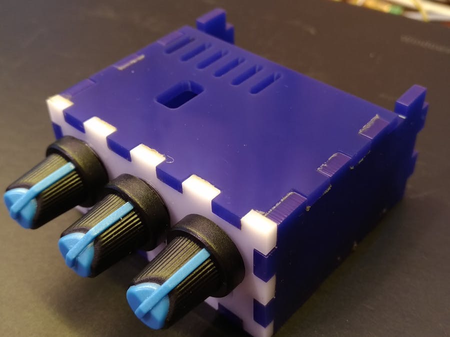
1 / 3 • CD40106 (or HEF40106) hex schmitt trigger NOT gate is shown at the back of the board.
- No microcontroller used. using a well known CMOS IC, available cheaply in this dark age of silicone shortage. it's a convenient use of silicone :)
- No regulator needed. the CD(HEF)40106 has a supply voltage range of 3~15 volts. works easily with many readily available power adapters.note that 74HC variants have a supply voltage range of 2~6 volts, so watch out!
- High current drive capability. using 3 MOSFETs. the MOSFETs PCB footprint allows for both TO252 and SOT23 packages. so you can choose a model that fits your desired current. note that the MOSFETs operating conditions should be compatible with supply voltage
- An onboard RGB LED. what if the strips are placed somewhere out of sight? an onboard RGB LED shows the current color mix.
- A Box! an easy to build, laser-cut box is available with schematics. it's glued together. no bolts or nuts are used for that.
Cons:yes everything should have "cons" because not everything is perfect.
- No ON-OFF switch.
- No animations or color effects.
The schematic is well known. it uses a schmitt trigger NOT gate as an oscillator, with charge/discharge path of capacitor separated using diodes, and controlled using a potentiometer.
The box designs are available as.svg files below.


Comments