



Hardware components | ||||||
 |
| × | 1 | |||
 |
| × | 1 | |||
 |
| × | 1 | |||
Software apps and online services | ||||||
 |
| |||||
This winter break, I was curious to learn about embedded Linux, and I learned how to create a kernel device driver for an MPU6050 accelerometer/gyroscope sensor. I started by understanding the register map of the MPU6050, identifying which registers needed to be configured, and then creating a simple driver to obtain sensor readings from user space. After validation, I began writing kernel device drivers, initially interacting through sysfs and later upgrading to the Industrial I/O (IIO) framework to obtain streaming data.
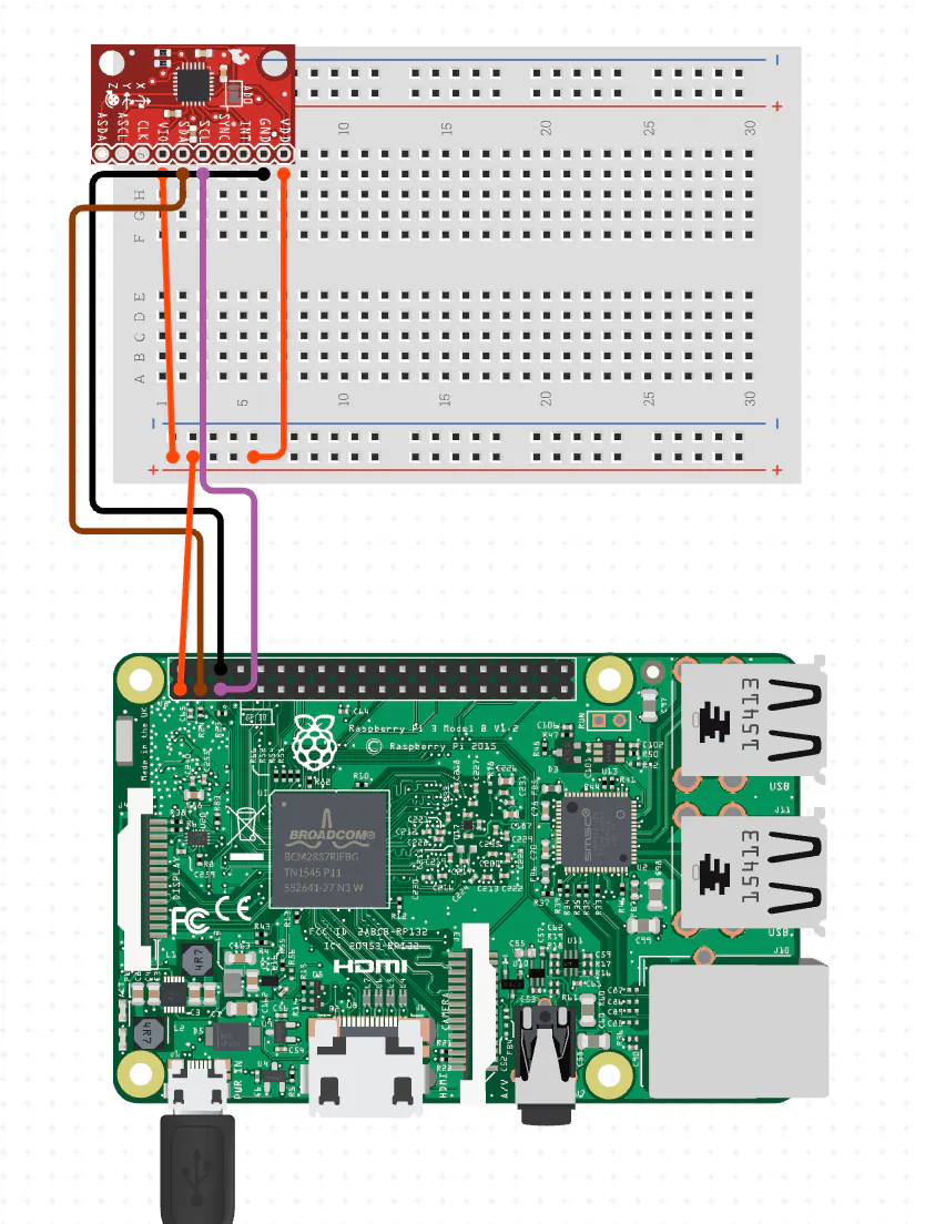
MPU6050 Sensor and its Register MapThe MPU6050 combines a 3-axis gyroscope and a 3-axis accelerometer, along with an on-board temperature sensor. Its interface is based on I²C, with a maximum frequency of 400 kHz. Interfacing it with the Raspberry Pi is fairly straightforward, as the sensor is directly connected to the standard I²C pins.
After reviewing the register map of the MPU6050 (link here), the following are the key registers required for powering up the device and reading sensor data. Note that all registers are 8 bits wide.
1. WHO_AM_I (0x75) : device identification
This should typically return the I2C address of the device. i.e 0x68 in this case.
2. PWR_MGMT_1 (0x6B) :
This register allows the user to configure the power mode and clock source. It also provides a bit for resetting the entire device, and a bit for disabling the temperature sensor.
3. ACCEL_CONFIG (0x1C) :
This register is used to configure the accelerometer's full scale range. Typically range includes ±2g / ±4g / ±8g / ±16g.
4. GYRO_CONFIG (0x1B) :
This register is used to configure the gyroscopes’ full scale range. Typical range includes ±250 deg/s / ±500 deg/s / ±1000 deg/s / ±2000 deg/s.
5. ACCEL_XOUT_H/L - ACCEL_ZOUT_H/L (0x3B–0x40) : X, Y, Z raw accelerometer data
These registers are read only registers. Each axis data is obtained from two 8-bit registers. Therefore, these 6 registers contains 3 raw 16-bit signed raw accelerometer readings, one for each axis
6. GYRO_XOUT_H/L - GYRO_XOUT_H/L (0x43-0x48) : X, Y, Z raw gyroscope data
Similar to accelerometer data, the gyroscope data is obtained from two 8-bit registers. Therefore, these 6 registers contains 3 raw 16-bit signed raw gyroscope readings, one for each axis
7. TEMP_OUT_H/L (0x41, 0x42) : Temperature readings.
16-bit signed value that stores the most recent temperature sensor measurement.
From the register map datasheet, temperature can be calculated as
Temperature in degrees C = (TEMP_OUT Register Value as a signed quantity)/340 + 36.53i2cdetect is a Linux command-line tool from the i2c-tools package that scans an I2C bus for connected devices, showing their addresses in a grid, useful for debugging and discovering hardware like sensors on devices like Raspberry Pi.
Once the I2C device is connected to the Raspberry Pi, a simple scan can be used to verify whether the device is detected:
$ i2cdetect -y 1
This should return the I2C address of the MPU6050.
Once the sensor is detected by the Raspberry Pi, the next step involves configuring the power management, as well as the accelerometer and gyroscope settings. This is done by writing to the appropriate registers. Sensor readings can then be obtained by reading from these registers. The snapshot below configures the MPU6050’s accelerometer with a sensitivity of ±2 g and returns the X, Y, and Z axis data.
Once the self-test verification is complete, a simple user-space device driver helps in understanding how the device should be communicated with before proceeding to a kernel-level driver. On the Raspberry Pi, the standard and recommended approach is to use /dev/i2c-* along with ioctl() via the i2c-dev interface.
<linux/i2c-dev.h> provides ioctl commands, constants, and structs that can be used with ioctl(), plus normal read() / write() system calls. The i2c-dev is a generic kernel driver for i2c which exposes each i2c bus as a character device.
The MPU6050 by default is attached to /dev/i2c-1 .
by combining ioctl with i2c-device, a simple helper functions are developed for open(), read() and write() operation.
Below is the code snippet that opens the i2c bus and binds it to the file descriptor.
int i2c_open(const char* i2c_dev_name, uint8_t address)
{
	int fd=open(i2c_dev_name,O_RDWR);
	if(fd < 0)
	{
		perror("Failed to open I2C driver\n");
		return -1;
	}
	if(ioctl(fd,I2C_SLAVE, address)<0)
	{
		perror("Failed to set I2C address\n");
		close(fd);
		return -1;
	}
	return fd;
}
Here, fd is a file descriptor that binds to the I2c driver. Thus, each read and write operation is referenced using fd, which goes into the kernel’s I2C stack. In effect, fd represents the combination of the I2C bus /dev/i2c-1 and the device address 0x68.
Given that each register of the MPU6050 is 1 byte long, and each axis of data (whether accel or gyro) are obtained from 2 registers. for e.g. ACCEL_XOUT_H and ACCEL_XOUT_L combines to form a 16-bit X-axis accelerometer data, the read( ) is modified such that it reads a certain number of bytes from a starting address.
Below is the helper function for reading an I2C register.
int i2c_read(int fd, uint8_t reg, uint8_t * val, uint8_t bytes_to_read)
{
if (write(fd, ®, 1) != 1) {
perror("I2C register select failed");
return -1;
}
if (read(fd, val, bytes_to_read) != bytes_to_read) {
perror("I2C read failed");
return -1;
}
return 0;
}The I2c write() send 2 bytes in a single I2C transaction to the currently selected slave. The first byte is interpreted by the MPU6050 as the register address and the second as the value to be written, forming a single I2C transaction consisting of a start condition, slave address, register byte, data byte, and stop condition.
int i2c_write(int fd, uint8_t reg, uint8_t val)
{
	 uint8_t buf[2] = { reg, val };

    if (write(fd, buf, 2) != 2) {
        perror("I2C write failed");
        return -1;
    }
    return 0;
}
Output
Displays the accelerometer, gyroscope and timestamp information captured every second.
A device tree is a data structure describing a computer's hardware components for the OS kernel, separating hardware details from the kernel code to enable portability and reduce duplication, especially in embedded systems. In short, the device tree specifies where the I2C device is located, its address, and a string that describes the device. This same string is used by the kernel device driver to probe and bind to the module.
Below represents the device tree of my MPU6050 module.
/dts-v1/;
/plugin/;

/ {
    compatible = "brcm,bcm2711";

    fragment@0 {
        target = <&i2c1>;
        __overlay__ {
            #address-cells = <1>;
            #size-cells = <0>;

            mpu6050_test@68 {
                compatible = "invensense,mpu6050_test";
                reg = <0x68>;
            };
        };
    };
};
The key parameters for the device tree are
- Mentioning that the device is an overlay, not a full device tree.
/dts-v1/;
/plugin/; - Attaching the device to the existing I2C bus. "&i2c1" is the label already defined in the base DT
fragment@0 {
target = <&i2c1>; - Choosing the compatible string for referencing. Its syntax is <vendor>,<device>. "mpu6050_test" is the string used in the device tree.
mpu6050@68 {
            compatible = "invensense,mpu6050_test";
            reg = <0x68>;
        };
    };
Steps involved in creating the I2C device using Device tree:
1. Compiling the overlay : The .dts file must be converted to its binary blob .dtbo. The "@" is required for overlays.
$ dtc -@ -I dts -O dtb -o mpu6050_test.dtbo mpu6050_test.dts2. Loading the Overlay : This involves loading the .dtbo file to /boot/firmware/overlays/
$ sudo cp mpu6050_test.dtbo /boot/firmware/overlays/3. Adding the overlay to config.txt : The line dtoverlay=mpu6050_test must be added to /boot/firmware/config.txt
Once loaded, the kernel creates the I2C device. It can be verified from here.
I2C drivers are probed only if a device node exists and matches the driver. It tells whether the kernel driver is able to communicate with the hardware from the device tree created in the previous step.
The basic skeleton code checks if the I2C device is probed. i.e the MPU6050 returns its own address by reading from its register 0x75.
static struct i2c_driver my_i2c_driver = {
.driver = {
.name = "mpu6050_test",   // MUST be unique
.of_match_table = my_of_match,
},
.probe  = my_probe,
.remove = my_remove,
};
.probe and .remove are functions overridden by my_probe and my_remove. In-order to know the function parameters and its return arguments, bootlin.com is an excellent platform containing a publicly accessible and searchable online interface to the official mainline Linux kernel source code.
Steps involved for obtaining the linux kernel source code.
1. Get the linux kernel version:
2. From bootlin.com, use the search bar to search for keyworks. For e.g. "i2c_driver" and naviage to the .h file containing the search result. For this use case, its the i2c.h file.
3. Check the source code for the version matching on the pi(step-1).
The I2C core invokes my_probe and my_remove via the .probe and .remove function pointers. Both the functions are overridden by taking reference from the main source code.
The probe() is called once the kernel module is loaded. This reads the register 0x75 of the I2C device using smbus helper function.
static int my_probe(struct i2c_client *client)
{
int whoami = i2c_smbus_read_byte_data(client, 0x75);
//dev_info(&client->dev, "I2C device probed\n");
dev_info(&client->dev, "WHO_AM_I = 0x%x\n", whoami);
return 0;
}
Once the module is unloaded, the kernel log must display the status that the device is removed.
static void my_remove(struct i2c_client *client)
{
dev_info(&client->dev, "I2C device removed\n");
}
Device Tree Mapping
For device tree based probing, the device tree string must be mentioned in the OF match table. Below is an example of how _of_match_table structure elements are obtained:
device_driver is part of i2c_driver and of_match_table is a pointer to structure of_device_id.
Thus, we exactly need to navigate to of_device_id to know its structure elements.
The <vendor>,<device> is set same as it was mentioned in the device tree to probe without any error.
static const struct of_device_id my_of_match[] = {
{ .compatible = "invensense,mpu6050-test" },
{ }
};
MODULE_DEVICE_TABLE(of, my_of_match);
Once the kernel module is loaded, this is the desired output:
Once the I2c device is probed, the next step involves exposing a clean, kernel-style interface to userspace. One of the easiest way to expose the user with the sensor data is using sysfs.
sysfs is a virtual filesystem that exposes kernel objects, devices, and driver attributes to user space. In sysfs, devices, drivers, kernel, buses and classes are represented as directories and files. From this approach, the sensor attributes are exposed as files and can be read as:
/sys/bus/i2c/devices/1-0068/accel //contains accelerometer (X, Y and Z axis) dataSteps involved in creating a sysfs kernel driver:
1. Deciding the sysfs attribute:accel: for displaying accelerometer axis data.gyro : for displaying gyroscope axis data.
2. Creating show() callbacks:
Callback function to read the register and print the result as a string. The example below is a callback function used to read the accelerometer data.
Note that the attribute name should match before _show. For e.g. the sysfs attribute for accelerometer is accel, so the callback function is accel_show().
static ssize_t accel_show(struct device *dev, struct device_attribute *attr, char *buf)
{
struct i2c_client *client = to_i2c_client(dev);
struct mpu6050_data *data = i2c_get_clientdata(client);
//int val;
mutex_lock(&data->lock);
int16_t accel_x = mpu6050_read_word(client, MPU6050_ACCEL_XOUT_H);
int16_t accel_y = mpu6050_read_word(client, MPU6050_ACCEL_XOUT_H+2);
int16_t accel_z = mpu6050_read_word(client, MPU6050_ACCEL_XOUT_H+4);
mutex_unlock(&data->lock);
// if (accel_x  < 0 || accel_y <0|| accel_z<0)
//    return accel_x;
return sprintf(buf, "X: %d, Y: %d, Z: %d\n", accel_x,accel_y,accel_z);
}
3. Define device attributes :
Each sysfs file is represented by a device_attribute. This binds the filename and show() callback
static DEVICE_ATTR_RO(accel);4. Creating and removing sysfs entries in probe() and remove() :
In probe() we create the sysfs entries. this creates
/sys/bus/i2c/devices/1-0068/accel
/sys/bus/i2c/devices/1-0068/gyro
The following lines are added to probe to create the entries:
/* store pointer for later use in sysfs callbacks */
i2c_set_clientdata(client, data);
/* create sysfs attributes */
device_create_file(&client->dev, &dev_attr_accel);
device_create_file(&client->dev, &dev_attr_gyro);
In remove() we perform a cleanup to safely unload the module. The entries are removed once the module is unloaded.
static void my_remove(struct i2c_client *client)
{
device_remove_file(&client->dev, &dev_attr_accel);
device_remove_file(&client->dev, &dev_attr_gyro);
dev_info(&client->dev, "I2C device removed\n");
}
Testing from the user space
From a terminal, we check the kernel log and check for messages
From another terminal, we load the module and read 1 sample of accelerometer and gyroscope readings. So far, everything seems to be working fine.
The Industrial IO (IIO) a dedicated subsystem within the Linux Kernel designed to provide a unified framework for drivers that interact with analog-to-digital converters (ADCs), digital-to-analog converters (DACs), and various types of sensors. It is ideal for MPU6050 because it can produce continuous data, contains multiple channels and can require buffered streaming.
From the user space, IIO supports configuration of devices and reading/writing data at low speeds via the /sys/bus/iio/devices/iio:deviceX/ directory structure. It can also support high-speed, buffered data acquisition using standard file operations from a character device. When it comes to sysfs, an advantage of IIO is that we need not create sysfs files manually. Instead we describe channels. The IIO core creates sysfs automatically.
IIO channels
An IIO channel can be described as a measurable signal exposed by the sensor device. For the MPU6050, the signals can be aceel_x, accel_y, accel_z, gyro_x, gryo_y, gyro_z, temp. Each channel automatically generates sysfs files.
This is a sample channel for X-axis of accelerometer:
/* Accelerometer X */
    {
        .type = IIO_ACCEL,
        .modified = 1,
        .channel2 = IIO_MOD_X,
        .info_mask_separate = BIT(IIO_CHAN_INFO_RAW),
        .scan_index = 0,
        .scan_type = {
            .sign = 's',
            .realbits = 16,
            .storagebits = 16,
            .shift = 0,
            .endianness = IIO_BE,
        },
    },
Explanation:
.type = IIO_ACCELSpecifies character "ACCEL" to describe an accerlerometer..modified = 1tells that this is a sub-category of "ACCEL".channel2 = IIO_MOD_XSpecified channel X of accelerometer.info_mask_separate = BIT(IIO_CHAN_INFO_RAW)IIO what information userspace can request.scan_index = 0determines the order in which data appears in the buffer
Here is how the channel assignment corresponds to the channel name:
IIO_ACCEL + IIO_MOD_X + IIO_CHAN_INFO_RAW = in_accel_x_raw
Note that the channel type by default is set as input, so we need not explicitly set it..sign = 's'Describes a signed bit.realbits = 16represents number of valid data bits. 16-bits in this case.storagebits = 16represents how many bits used in memory.shift = 0tells the number of bits to right-shift after reading. Not required for this case.endianness = IIO_BErepresents that the data is big-endian since we read the MSB first.
Finally, the channel for the X-axis accelerometer can be read using sysfs style where the channel is stored as
/sys/bus/iio/devices/iio:deviceX/in_accel_x_rawSince the process has to be repeated for all the channels(3 for accelerometer, 3 for gyro and 1 for temperature), a common macro can be used to prevent duplication. The macro below can be used for creating X,Y and Z axis of the accelerometer
#define MPU6050_ACCEL_CHAN(_axis, _idx) {        \
.type = IIO_ACCEL,                           \
.modified = 1,                               \
.channel2 = _axis,                           \
.info_mask_separate = BIT(IIO_CHAN_INFO_RAW),\
.scan_index = _idx,                          \
.scan_type = {                               \
.sign = 's',                             \
.realbits = 16,                          \
.storagebits = 16,                       \
.shift = 0,                              \
.endianness = IIO_BE,                    \
},                                           \
}The existing driver using IIO does not support continuous streaming yet. In IIO, continuous reading is done via IIO buffers + triggers, not by repeatedly calling read_raw().
Below is a high-level overview of how continuous reading can be obtained:
Trigger fires (timer / IRQ)
         ↓
mpu6050_trigger_handler()
         ↓
Read X/Y/Z registers once
         ↓
Pack scan data (X,Y,Z)
         ↓
iio_push_to_buffers()
         ↓
userspace read()
Below are the changes needed to enable continuous streaming using triggers:
1. Adding a triggered buffer in probe()
ret = devm_iio_triggered_buffer_setup(
&client->dev,
indio_dev,
NULL,                        /* preenable */
mpu6050_trigger_handler,     /* pollfunc */
NULL);                       /* postdisable */
2. Implementation of trigger handler:
Whenever a trigger is called, the function below is invoked. read_raw() is not used in buffered mode.
static irqreturn_t mpu6050_trigger_handler(int irq, void *p)
{
struct iio_poll_func *pf = p;
struct iio_dev *indio_dev = pf->indio_dev;
struct mpu6050_data *data = iio_priv(indio_dev);
s16 accel[3];
mutex_lock(&data->lock);
accel[0] = mpu6050_read_word(data->client, MPU6050_ACCEL_XOUT_H);
accel[1] = mpu6050_read_word(data->client, MPU6050_ACCEL_XOUT_H + 2);
accel[2] = mpu6050_read_word(data->client, MPU6050_ACCEL_XOUT_H + 4);
mutex_unlock(&data->lock);
iio_push_to_buffers(indio_dev, accel);
iio_trigger_notify_done(indio_dev->trig);
return IRQ_HANDLED;
}
3. Attaching a Trigger:
Triggers can be implemented in hardware (from INT pin of MPU6050) or software based. I have implemented a software trigger using sysfs. It requires the following modules to be added to the kernel
sudo modprobe iio-trig-sysfs
sudo modprobe industrialio
sudo modprobe industrialio-triggered-buffer
Once loaded, we will have access to /sys/bus/iio/devices/
Once the kernel module is loaded, we create a trigger from here
$ echo 0 | sudo tee /sys/bus/iio/devices/iio_sysfs_trigger/add_triggerThis creates trigger0. We then check the name attached to trigger0.
$ cat /sys/bus/iio/devices/trigger0This returns the name sysfstrig0. We then attach the trigger to our iio device iio:device0.
$ echo sysfstrig0 | sudo tee /sys/bus/iio/devices/iio:device0/trigger/current_trigger4. Enable the buffer
We first enable the scan elements
$ echo 1 | sudo tee /sys/bus/iio/devices/iio:device0/scan_elements/in_accel_x_en
$ echo 1 | sudo tee /sys/bus/iio/devices/iio:device0/scan_elements/in_accel_y_en
$ echo 1 | sudo tee /sys/bus/iio/devices/iio:device0/scan_elements/in_accel_z_en
Then we set the buffer length and then enable the buffer
$ echo 4 | sudo tee /sys/bus/iio/devices/iio:device0/buffer/length
$ echo 1 | sudo tee /sys/bus/iio/devices/iio:device0/buffer/enableFrom terminal-1, we obtain the kernel logs
From terminal-2 we fire the trigger
$ echo 1 | sudo tee /sys/bus/iio/devices/iio_sysfs_trigger/trigger_nowTerminal-3 reads the raw buffer stream from the character device
Continuous streaming Output
Terminal-1 reads from the character device
$ sudo cat /dev/iio:device0 | hexdump -v -e '3/2 "%6d " "\n"'Terminal-2 continuously fires the sysfs trigger
while true; do echo 1 | sudo tee trigger_now; sleep 0.01; done1. Disable iio buffer
$ cat /sys/bus/iio/devices/iio:device0/buffer/enable
$ echo 0 | sudo tee /sys/bus/iio/devices/iio:device0/buffer/enable
2. detach the trigger
$ echo "" | sudo tee /sys/bus/iio/devices/iio:device0/trigger/current_trigger3. kill user-space readers
a. Get process ID:
$ sudo lsof /dev/iio:device0b. Kill the process:
$ sudo kill -9 <PID>4. Remove kernel module


Comments