
Hardware components | ||||||
 |
| × | 1 | |||
| × | 1 | ||||
 |
| × | 1 | |||
 |
| × | 1 | |||
 |
| × | 1 | |||
 |
| × | 1 | |||
 |
| × | 1 | |||
Software apps and online services | ||||||
 |
| |||||
| ||||||
| ||||||
 |
| |||||
Due to recent technological advances, our homes as well as other organizations have been modernized to a great extent. Although many precautions and other safety measures are taken to prevent as well as control the occurrence of fires, there are still some things which are out of our hand. We often hear about instances where buildings are on fire, but by the time the firemen arrive, the entire property has been destroyed. Moreover, in their state of panic, the owners are not able to think quickly and hence the damage done extends to a higher level. This project "Fire Detection and Alert System" aims to solve this problem.
1.INTRODUCTION
This project makes use of the upcoming concept of IoT- Internet of Things. Various sensors are interface with a variety of devices so that they can be connected to the internet and then can be controlled remotely.
This project makes use of a flame sensor to detect the occurrence of fires in the particular apartment. If a fire is detected by the sensor, then three things happen:
- The buzzer starts ringing in the apartment and if someone is present there, then they are alerted about it.
- An email alert is also sent to the owner of the apartment so that he can take an appropriate course of action.
- Also, the LED at the security desk of the society begins to glow, so that the security personnel are notified and then they can reach the apartment with fire extinguishers. In case of extensive fires, they can also immediately contact the fire men.
2.COMPONENTS
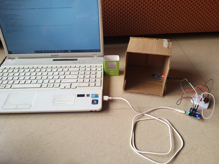
The image below shows all the components that have been used to create the circuit of this project. The name of the components as well as their links have been provided above.
3.CIRCUITCONNECTIONS
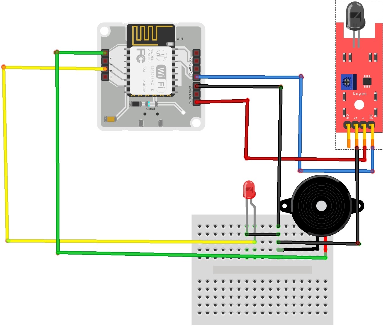
The details of the connection done are provided below:
- Flame Sensor: The output pin of the flame sensor is connected to the digital pin 0 of the Bolt wi-fi Module. The VCC pin is Connected to 5V pin of the wi-fi module. The ground pin is connected to the breadboard.
- LED: The positive end is connected to digital pin 3. The negative end is connected to ground.
- Buzzer: The positive end is connected to the digital pin 1. The negatuve end is connected to ground.
All the connections are connected to the ground appropriately. Also for better understanding, use a breadboard for all the connections.
The schematic diagram at the end provides a simplified diagram of the connections.
4.HOWDOESITWORK?
- When no fire is detected by the system, then the sensor returns output=HIGH and the output screen shows that everything is normal and no fire has been detected.
- When the system detects a fire, then the sensor sends output=LOW and the buzzer in the apartment starts ringing and the LED at security desk starts glowing. Also, an alert email is sent to the owner to notify him about the situation.
- Manual control over the LED as well as buzzer is also provided using a web page.
5.DEMONSTRATIONVIDEO
6.STEPS
- Connect the circuit as per guidelines given in step 3.
- Connect your Bolt Device to the Bolt Cloud as per instructions given at https://trainings.boltiot.com/. and check if the status of your device is online. (if device show's offline try troubleshooting the problems as given by https://trainings.boltiot.com/.)
- Create a new product on the bolt cloud and give a name for the product and select done.
- Click on configure and go to the code section. Select the html extension and paste the code given below to create a web page for manual control over the LED and buzzer.
<!DOCTYPE html>
<html>
<head>
<title>Alert Control</title>
<script type="text/javascript" src="https://cloud.boltiot.com/static/js/boltCommands.js"></script>
<script>
setKey('{{ApiKey}}','{{Name}}');
</script>
</head>
<body bgcolor="grey">
<h1 align="center"> Fire Detection and Alert System</h1>
<br>
<center><h2 font size=50px>Buzzer Controller</h2>
<button onclick="digitalWrite(1, 'HIGH');">ON</button>
<button onclick="digitalWrite(1, 'LOW');">OFF</button>
</center>
<br>
<br>
<center><h2 font size=50px>Security Alert(LED)</h2>
<button onclick="digitalWrite(3, 'HIGH');">ON</button>
<button onclick="digitalWrite(3, 'LOW');">OFF</button>
</center>
</body>- Create an account on mailgun so as to send email alerts to the user. You can follow steps given on https://trainings.boltiot.com/. Note: Use (test@your sandbox url) for senders email.
- Create a configuration file in python to provide necessary credentials for sending emails.
API_KEY = "API key from BOLT cloud"
DEVICE_ID = "BOLT*******"
MAILGUN_API_KEY = "api key from mailgun account"
SANDBOX_URL = "url obtained from sandbox"
SENDER_EMAIL = "email id from sandbox"
RECIPIENT_EMAIL = "your_email"
FRAME_SIZE = "10"
MUL_FACTOR = "6"
- Create another file in python which sends alerts depending on the sensor output. The code is given below.
import email_config
import time, json
from boltiot import Bolt,Email
api_key="api key from bolt"
device_id="BOLT******"
mybolt= Bolt(api_key, device_id)
mailer = Email(email_config.MAILGUN_API_KEY, email_config.SANDBOX_URL, email_config.SENDER_EMAIL, email_config.RECIPIENT_EMAIL)
HIGH = 1
LOW = 0
while True:
fire = mybolt.digitalRead(0)
parsed_response = json.loads(fire)
print ("Parsed response is")
print (parsed_response)
sensor = int(parsed_response["value"])
if sensor==0:
print ("Fire detected")
print ("Sending mail")
mybolt.digitalWrite('1','HIGH')
mybolt.digitalWrite('3','HIGH')
response = mailer.send_email("Alert","Fire has been detected in your apartment! The security has also been alerted.")
else:
print ("No fire detected.")
mybolt.digitalWrite('1','LOW')
mybolt.digitalWrite('3','LOW')
time.sleep(10)- Compile the code and then rectify the errors (if any). If everything seems appropriate. Connect the Bolt wi-fi module to the power supply and run the code.
- EMAIL ALERTS


Comments