



Hardware components | ||||||
 |
| × | 1 | |||
| × | 1 | ||||
| × | 1 | ||||
| × | 1 | ||||
| × | 1 | ||||
| × | 1 | ||||
 |
| × | 1 | |||
| × | 1 | ||||
| × | 1 | ||||
 |
| × | 1 | |||
Software apps and online services | ||||||
 |
| |||||
Hand tools and fabrication machines | ||||||
| ||||||
 |
| |||||
 |
| |||||
| ||||||
Living in Hayama on the Miura Peninsula of the Japanese archipelago, I am constantly reminded of the beauty and power of the seasons.
The incredibly warm winter sunlight that softens the harsh winds, the fierce spring gales that sweep through the coast, the cooling sea breeze of summer carrying the scent of the tide, and the ginkgo trees dancing in the autumn wind, each turning yellow at its own unique pace. I feel a deep sense of gratitude to live in an environment where nature's presence is so profoundly felt.
For me, the wind — whenever and wherever it blows — traces back to my childhood. Every night before bed, I loved listening to the rustling of leaves in the night breeze. It was the sound of a large poplar tree planted by my grandmother to commemorate my birth. In Japan, the poplar trees of Biei Town in Hokkaido are famous. (https://ja.wikipedia.org/wiki/%E3%83%9D%E3%83%97%E3%83%A9) If you felt something strange, your instincts are correct. As you know, the poplar becomes too big to be in a small residential area in Japan. My mother never said so, however, I'm thinking she perhaps knew it but deliberately chose it.
Because, my grandmother was a resilient woman who met my grandfather at "Manchuria", a land stretching to the horizon endlessly in Northeast China, during WWII. Just after the war (yes, the war should have ended), she was a rare survivor who escaped the overwhelming Soviet persistent offensive robbing and narrowly returned to Japan. In our small but safe residential area in Southern Osaka Prefecture, that poplar grew unnaturally tall, surpassing our living house by the time I was 17. Because it became a lightning hazard, we eventually had to cut it down.
Though the tree is gone, the "SARI-SARI" sound of its leaves remains etched in my heart — no, I should say — it shaped my heart. Today, as I face the fierce gales of Hayama, I find myself still trying to capture and understand what the sound of the wind means through my engineering.
This project is a humble attempt to harmonize technology with these natural elements. My goal is to ensure that my prototypes can continue to survive even long after I am gone and function as guardians within the same environment I call my place of peace and security.
Project ScopeThis guide focuses on two essential pillars for field deployment, explained simply for the world-wide DIY beginners using common hand tools and cost-effective materials.
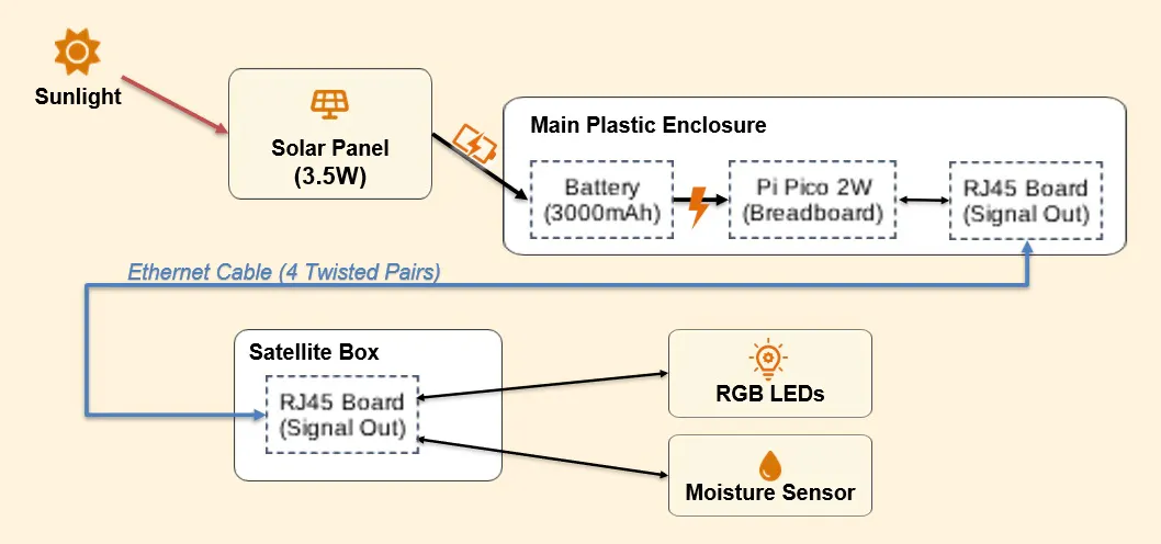
To keep the Raspberry Pi Pico 2W connected to the Wi-Fi and allow my HomeServer to send real-time commands—such as making the Haniwa’s eyes flash—we must first understand the power consumption of the Wi-Fi chip (CYW43). While transmitting data naturally consumes significant power, we can save energy by putting the chip into a "doze" state where it only listens for incoming packets. Even in this power-saving mode, the system will continuously consume approximately 20[mA]. If we connect it to a mobile battery with an effective capacity of 3, 000[mAh], the system is calculated to last for ~6[days].
3000[mAh] / 20[mA] /24 [h/d] = 6.25[d]
cyw43_arch_enable_sta_mode();
cyw43_wifi_pm(&cyw43_state,
               cyw43_pm_value(CYW43_PM2_POWERSAVE_MODE, 200, 1, 1, 5));
watchdog_update();
If we have even one sunny day during that 6-day period, we can keep the cycle going. Given a solar input of
3[W] / 5[V] * 1000 = 600[mA]
just 5 hours of warm sunlight should be enough to fully recharge the 3, 000[mAh] battery. With this setup, even if I were to pass away decades from now, this system would continue to draw breath, tirelessly supplying power to the Pico 2W. The Legacy Battery and the Pass-through TestI searched through my storage and found an old friend: a 6, 700[mAh] mobile battery made by a Japanese manufacturer a many years ago.
It’s nearly a decade old (2018 on sale) and long discontinued, so it’s safer to assume its actual capacity has dropped to about half. Still, it might provide at least 3, 000[mAh]. Let’s put it to work. The first thing to check was whether this battery supports "pass-through" charging—the ability to provide power to a device while simultaneously being charged itself.
To test this, I used a DIY bedside lamp I had previously made by stuffing an LED string light into a small wine bottle. I bought this bottle at a hotel during my very first business trip abroad — a memory I still cherish. I connected the battery to a wall outlet via USB micro-B and plugged the LED string into the battery’s USB Type-A port.
The wine bottle emitted a gentle, steady glow. Success. It was time to bring this ancient battery into my latest project. Selecting the Solar Panel to charge a 3, 000[mAh] battery in 5[hours] at a standard USB voltage of 5[V], I needed a solar panel with a generating capacity of at least 3[W]. I decided on a 3.5[W] panel made for security cameras used outside of many houses. It’s a modest setup, but it feels just right for this project.
With that, the selection of power supply components and basic testing are complete. Next up is waterproofing the circuit. My hands are shaking with fear of damaging something important, but I'll give it a try tomorrow morning, good night...
1'. Refining Resilience: Introducing the WatchdogWhen I woke up, however, the Pico had frozen—likely due to a TCP connection failure caused by something like microwave interference in the kitchen.
To improve resilience, I introduced a Watchdog Timer. It’s a simple yet powerful tool to ensure the system reboots automatically if it hangs.
When implementing it, keep these three points in mind:
- The 8-Second Rule: On the Raspberry Pi Pico, the maximum timeout is 8 seconds. You must feed the watchdog within this window.
- Preventing Infinite Boot Loops: If you forget to call update() after a long process, the watchdog will keep "spawn-killing" your Pico before it even starts its game.
- Code Structure: Don’t forget to #include the necessary headers not just in haniwa_main.cpp, but also in haniwa_connector.cpp and haniwa_monitor.cpp respectively if they handle independent tasks.
Like this:
#include "hardware/watchdog.h"
// In a loop
    // Long processing time of up to 5 seconds
    int state = cyw43_arch_wifi_connect_timeout_ms(
                WIFI_SSID, WIFI_PASSWORD, CYW43_AUTH_WPA2_AES_PSK, 5000
    );
    // Always feed your guard dog after a long period of work.
    watchdog_update();
    // If you absolutely need them to sleep for more than 8 seconds,
    // you can use a for loop.
    for (int i = 0; i < 10; i++) {
        sleep_ms(1000);
        watchdog_update(); // Do not forget feeding
}The Ethernet Bridge: Repurposing Household Surplus for Noise-Resistant Signal TransferWhen you move to a new house or switch internet service providers (ISPs), you often find yourself with extra Ethernet cables — those "leftovers" from FTTH gateway router rentals that tend to pile up in a drawer. In this project, we’ll put one of those dormant cables to work as a reliable bridge between our main waterproof enclosure and the satellite plastic box.
Why Ethernet?I’ll be honest: I’m not skilled enough to solder wires directly onto those tiny RJ45 pins. However, using RJ45 breakout boards solves this perfectly. As you know, an Ethernet cable consists of eight internal wires organized into four twisted pairs. This structure is inherently robust against external electromagnetic noise, even over long-distance transmissions across a garden.
Implementation Strategy:To build this bridge, I used two different types of breakout boards:
- On the main side: A board with a standard 2.54mm pitch header that plugs directly into my breadboard alongside the Pi Pico 2W.
- On the satellite side: A board with screw terminals, allowing me to securely fasten jumper wires for the RGB LEDs and the soil moisture sensor without worrying about them vibrating loose in the wind.
Verification with a Multimeter:Before closing the boxes, I used a multimeter in resistance mode to map the pinouts. Since some breakout boards can be confusing, it’s essential to confirm continuity between the breadboard pins and the screw terminals. In my case, as shown in the photo, the pinout was mirrored: Pin 1 on the far-right of the connector corresponded to the far-left screw terminal.
One Critical Warning: Straight vs. CrossoverWhile rare nowadays, "Crossover" Ethernet cables still exist in the world. Unlike standard "Straight-through" cables, the internal pairs in a crossover cable are swapped.
I strongly recommend using a standard Straight-through cable. If you must use a crossover cable, be extremely careful; you will need to re-verify every single pin with a tester and adjust your component wiring accordingly. One wrong connection here, and your sensors are gone!
Switching to Common Anode: Embracing "Active Low" LogicIn this step, I made a small but significant change to the circuit: switching from a Common Cathode to a Common Anode RGB LED to use simple one LED. While it might seem counter-intuitive at first for mechanical engineers like myself, understanding this is a vital "rite of passage" for any electronics hobbyist.
The Wiring Change:Instead of connecting the longest pin (Common) to GND (Pin18), I connected it to the 3.3V pin (Pin36) of the Pi Pico 2W. The Red, Green, and Blue pins are still connected to the GPIOs via resistors.
What is "Active Low"?With this setup, the logic is reversed. This is known as Active Low: Write 0 (LOW): The GPIO sinks the current, and the LED turns ON. Write 1 (HIGH): There is no voltage difference, and the LED turns OFF.
Many professional microcontrollers and industrial sensors prefer this "sinking" method because it is often more electrically stable and efficient. In my code, I simply initialized the pins to 1 to keep them off at startup.
The code modification is simple: in haniwa_monitor.cpp, simply reverse the off 0 and on 1 signals, changing off 1 to on 0. Since haniwa_main.cpp is already set up as the command center, haniwa_connector.cpp handles communication only, and haniwa_monitor handles how the various sensors operate, you only need to edit haniwa_monitor.
void turn_off_all_leds(void) {
     gpio_put(LED_RED, 1);    // 1. HIGH means turn off LED
     gpio_put(LED_GREEN, 1);  // 1. HIGH means turn off LED
     gpio_put(LED_BLUE, 1);  // 1. HIGH means turn off LED
}
Take a look at the movie below — seeing the RGB colors shine with "reversed" logic felt like a celebration! Sorry, but I was so excited. It's fun to get into a new sense of things. Please be careful not to get motion sickness while watching, my hands are shaking as I hold the camera, indicating I'm just so happy.
The Problem: A Tiny "Ghost" in the CircuitThe joy was short-lived. Even when the LEDs were supposed to be OFF, I noticed they were faintly glowing in the dark. A "Ghost" had appeared!
After a closer look, I realized there was a tiny potential difference between the 3.3V power rail and the GPIO pins. This small leak was enough to light up my high-efficiency RGB LED. Since I've carefully calculated my power budget to run this system for weeks on a single charge, this "energy leak" was unacceptable.
The Solution: High-Side SwitchingI recalled a technique I used before: using a GPIO pin as a power source only when needed to save energy. This is known as High-Side Switching, and it’s a standard practice even among experts.
The ImplementationFirst — safety first — I unplugged the Pico. Then, I moved the jumper wire from Pin36 (3V3) to Pin22 (GP17).
I updated the code to control the power flow:
- Keep GP17 LOW by default to completely cut off the power to the LED's anode.
- Set GP17 to HIGH only when I need to blink the LEDs.
- Since LEDs don't allow current to flow in reverse, keeping GP17 at 0V safely "locks" the circuit.
The code is like this:
// Define pin numbers depending on your microcontroller board
const uint LED_SOURCE  = 17;
const uint LED_RED     = 13;
const uint LED_GREEN   = 14;
const uint LED_BLUE    = 15;

// Make a function to turn off all LEDs
void turn_off_all_leds(void) {
    gpio_put(LED_SOURCE, 0);
    gpio_put(LED_RED, 1);
    gpio_put(LED_GREEN, 1);
    gpio_put(LED_BLUE, 1);
}

// Make a function to ready all LEDs
void ready_all_leds(void) {
    gpio_put(LED_SOURCE, 1);
    sleep_ms(20);
}

// Use above functions in controlling LEDs
void haniwa_led_blink_red(int seconds) {
    // Call "ready" at first
    ready_all_leds();
    for (int i = 0; i < seconds; i++) {
        gpio_put(LED_RED, 0);
        sleep_ms(500);
        gpio_put(LED_RED, 1);
        sleep_ms(500);
        watchdog_update();
    }
    // Call "turn-off" immediately after use to save energy
    turn_off_all_leds();
}Okay, now, the ghost is gone, and my energy efficiency is back on track! Before we think about waterproofing, let's tidy up the breadboard a bit so that we can make effective use of the 8 pins of the Ethernet cable. Arrange them in a straight line from right to left in the following order: LED-Red, LED-COM, LED-Green, LED-Blue, Not-Used, SoilMoisture-GND, SoilMoisture-VCC, and SoilMoisture-Signal.
Back in my university days, when I built my own PCs, I had some leftover parts tucked away in a drawer. Let's see if I can find anything useful. I dug out some jack-to-pin jumper wires. There are exactly four of them: red, black, green, and blue. Great, this means I don't have to solder the four wires for the RGB LED. I'm not going to say "I mustn't run away, " (even I'm called as "Shinji-kun.") You don't have to ride something you don't want to ride. I'll run away from soldering as far as it takes. I wasn't taught that kind of such an advanced skill, by my father.
Looks like we've managed to escape. No pursuers can catch me now. Okay, while we have the chance, let's build a waterproof enclosure.
Fossilized clumps of soil containing life from 10 million years ago will protect the latest Pico from its greatest enemy: moisture.
Let's drill two holes for the cable exit. Now, I have something very important to tell all you DIY beginners: Always wear cut-resistant gloves when using drills or utility knives. If you don't have any on hand, stop working, absolutely stop. It might be unavoidable to get a small injury, but you absolutely must not get a serious injury that can be prevented. There is no development work in this world that you have to do at the risk of a lifelong injury, and there shouldn't be.
I still remember clearly that at the factory where I first worked, utility knives were completely banned. Because all the senior workers were getting injured so often, one of the executives, at his wit's end, banned the knives themselves from the company. I think it was a difficult decision, and some people probably mocked it. But thanks to that, I never got seriously injured during my seven years there. That says it all, and I don't think I've said anything more. At the time, I didn't fully understand the seriousness of the situation, but now I'm very grateful.
To protect against rain coming from above, I'll cut a horizontal hole just below the lid that's the perfect size for the cable. This way, the lid itself will act as a roof, allowing the water to drain down. Once I can secure the cable and close the lid, it's finished.
Let's finish waterproofing the satellite box.
For this kind of low-cost waterproofing, the kitchenware section of a 100-yen shop is very useful. I bought some small Tupperware containers; four for 100 yen. In this era of a weak yen, this price is a steal.
Imagine the actual receiver, place it against the mounting surface, make three cuts, and seal it with bathroom sealant. Waterproof any exposed wiring around the equipment with heat shrink tubing.
Haniwa's chef's hat:I bought a self standing funnel, and make it to a hat for my Haniwa. Look, Haniwa-san looks like he's become a head chef.
I went back to my room, wrapped heat-shrink tubing around the exposed contacts, sealed them with a lighter, and I glued thickly as "Bote-Bote" the soil moisture meter circuit with a glue gun. Now the Region-free Field-usable Off-grid Sensing Scarecrow System, made exclusively for the Haniwa Guardian, is complete.
So then, how should I let haniwa equip it? Come to think of it, I vaguely remember my grandmother tying her kimono sleeves using one string (we call it "Tasuki-gake") before she was cooking, cleaning or something needs to move quickly, so the hanging sleeves wouldn't get in the way. I'll attach the satellite box to Haniwa Guardian's back and secure it with one hemp string tied like "Tasuki-gake". That's a true Japanese solution!
Evolving HANIWAHaniwa Irrigatable Scarecrow has evolved into "Shin Haniwa Guardian", equipped with new gears.
When combining a solar panel with a mobile battery (pass-through charging), a notorious problem often occurs: a brief power drop (glitch) during the transition when the solar input cuts out and the battery switches to standalone discharge mode. Even though this lag lasts only a few hundred milliseconds (so I overlooked it during the LED Bottle Lantern test), it is long enough to cause the Raspberry Pi Pico 2W to brown out and reboot. Please look at this movie:
In short, the solution is very simple. To solve this and achieve the "Immortal Haniwa" that survives these switching glitches, you can simply add a 5.5V Supercapacitor between Pin 40 (VBUS) and Pin 38 (GND).
Why No External Diode is Needed:
You might think an external reverse-current protection diode is required to prevent the capacitor from discharging back into the power bank. However, thanks to the smart hardware design of the Raspberry Pi Pico 2W, it is not needed. The board already features an onboard Schottky barrier diode (D1) that inherently blocks the reverse current from VBUS back into the microUSB source.
Therefore, all you need to do is to connect the supercapacitor in parallel directly to the pins: Positive (+) to Pin 40 (VBUS), and Negative (-) to Pin 38 (GND).
My sincere apologies, everyone! I need to make a correction here. In the video, I showed that the system stays powered when the USB is unplugged, but the supercapacitor actually must be connected from Pin 39 (VSYS) to Pin 38 (GND). If you connect it to Pin 40 (VBUS) like I did, you won't be utilizing the Pico's built-in Schottky barrier diode, which is crucial for preventing reverse current during solar power transitions. Let's make sure to connect it to Pin 39 to make it truly resilient!
Note: Double-check the polarity before powering on, as supercapacitors are polarized components.
Sizing the Capacitor: How much capacity do we actually need to survive a typically larger 0.5-second (500ms) glitch? We can determine the required capacitance (C) using the following formula:
C = (I x t) / dV
Where, I is the estimated base current of Pico 2W during its sleep interval -> ~40[mA], t is the glitch duration to survive -> 0.5 sec., dV is the allowable voltage drop from 5.0V down to the regulator threshold of 4.0V -> 1.0V. i.e.,
C = (0.04 x 0.5) / 1.0 = 0.02[F]
While a standard 20,000uF electrolytic capacitor would be physically massive and impractical for a compact prototype box, a coin-sized 0.22F (220,000 µF) Supercapacitor is readily available and compact. Choosing a 0.22F capacitor provides more than 10 times the required buffer, keeping the Pico 2W alive for several seconds during power fluctuations. While a 1.0F capacitor is also an option, it introduces unnecessary inrush current and startup delays. Don't fill a massive swimming pool when a reliable bucket is all you need. The 0.22F capacity will be a sufficient, optimized, and elegant power-backup design.
A Warning on Polarity
Supercapacitors are polarized components. I’ll be honest, over my years of tinkering, I’ve accidentally fried quite a few components by reversing the positive and negative leads. It’s an incredibly easy mistake to make, so double-check your wiring before you use a new component in the actual circuit environment.
There are many ways to verify the polarity of your specific capacitor before plugging it into the breadboard (using a datasheet, testing with a multimeter, etc.). Take your time and find a method that works best for you.
Got stuck or confused? Don't worry! If you’re staring at your components and wondering "Which way does this go?", just leave a comment or drop a question below. I’d be happy to help you figure it out so you don't have to learn the hard way like I did.
ConclusionsThis project is dedicated to my grandmother, who passed away last winter.
I have been clumsy with my hands since I was a child. Even now, I still struggle with soldering. It may sound like an excuse, but the truth is, I never knew my father. He left home for someone else, just before I was even born. Among my possessions today are several hand tools he left behind — water pump pliers, screwdriver sets, box wrenches — but he was never there to teach me how to use them.
My mother, fearing I might accidentally start a fire, wouldn't let me touch a soldering iron, so I didn't own one until I became an adult. Everything I know, I had to learn by doing. I moved forward through countless minor injuries and by breaking many valuable things. Even now, I find my hand shaking almost too afraid of breaking something precious.
I remember a moment from my university days while learning nano-plating. The teaching assistant grew frustrated with my clumsiness. "How can a college student fail at something so easy way?" he scolded. "The quality of students has gone down. Didn't your father ever teach you anything?"
It was the same as always; with a forced, awkward smile, I said, "I’m sorry, but I don't have a father, as you know, right?"
After that, he fell silent and stopped teaching me altogether. I never thought simply he was a bad person; it was an era where adults usually left behind children who didn't perform well. Looking back, my retort was childish, too.
But it’s okay, no problem, I hold no grudges. Even before I was born, I think my father taught me just one thing that hating someone changes nothing. I had my grandmother, who raised me up to be bigger than a house, and I have my mother, who nurtured my ability to put experiences into words like these. My childhood was more than luxurious enough.
Just recently, I helped my daughter with her junior high school homework involving soldering. After explaining the safety and technique as carefully as I could (it might be too-much), she moved her own hands and succeeded. Do you understand what this means?
In this era of rapidly advancing AI, we cannot survive by simply passing on what we were taught. Sometimes, we must find a way to teach the new things we discovered ourselves — the things no adult ever told us.
However, perhaps — and I want to send a message of encouragement to all the highly-educated, white-collar workers who, like myself, may feel on the brink of despair jobs were taken by AI — it is only in such a real changing world that we get a chance to truly discover and express our unique skills and individual personalities uninterrupted by anyone's shallow words. Let’s continue to play this adventure game called life.
With deepest gratitude to my grandmother, who survived the bitter, dry cold of the continent and is now reading this from heaven.
Disclaimer- Personal Project: This project is a personal hobby and technical experiment. It is not affiliated with, sponsored by, or endorsed by any of the organizations mentioned.
- Accuracy & Responsibility: While I strive for technical and historical accuracy, I assume no responsibility for any issues or damages arising from the use of the information in this article. Everything is done at your own risk.
- Battery Safety: This project involves the use of aged lithium-ion batteries. Please be aware that old batteries may pose risks of swelling or fire; handle them with extreme caution and monitor their condition regularly.
- Handle with Care: I do NOT recommend getting injured. Always wear cut-resistant gloves when you use drills and utility knives to avoid injury. Most importantly, handle your soldering iron with extreme caution to prevent fires or burns. As I did, consider avoiding soldering altogether as an option.


Comments