


Hardware components | ||||||
| × | 4 | ||||
 |
| × | 1 | |||
| × | 1 | ||||
 |
| × | 2 | |||
 |
| × | 1 | |||
 |
| × | 1 | |||
Software apps and online services | ||||||
 |
| |||||
Hand tools and fabrication machines | ||||||
 |
| |||||
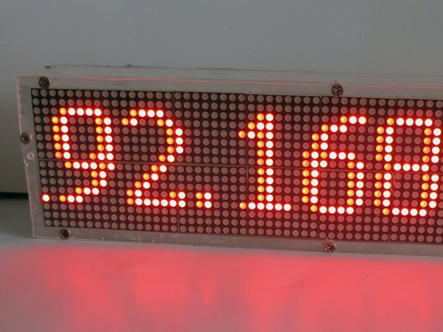
In the project I will show how to build a big enough 'creeping line' display of 16 max7219 led matrix modules. The display is managed by esp8266 micro controller and implements the WEB interface.
DemoHow to make itYou can connect to the display using a WEB browser, select font from the pull-down list menu, setup the display brightness and speed of the creeping text, and write the text to be displayed.
The main component of the display is a esp8266 micro controller. I used the ESP8266-12E one and several components to make it work: the PSB, ams1117-3.3 voltage regulator, capacitors. All these components are irrelevant if you use a NodeMCU or wemos development board. If you are a novice hardware engineer I would recommend you to use the development board.
The second component is a display modules. I used the 4-matrix module display units, 16 matrices combined together to build a big display 8x2 matrices or 64x16 pixels. These modules have max7219 IC which supports a SPI interface. Each matrix has 10 pins to be connected to the controller and to be cascaded to the next matrix. You should always connect the output pins of one matrix to the input pins of the next matrix.
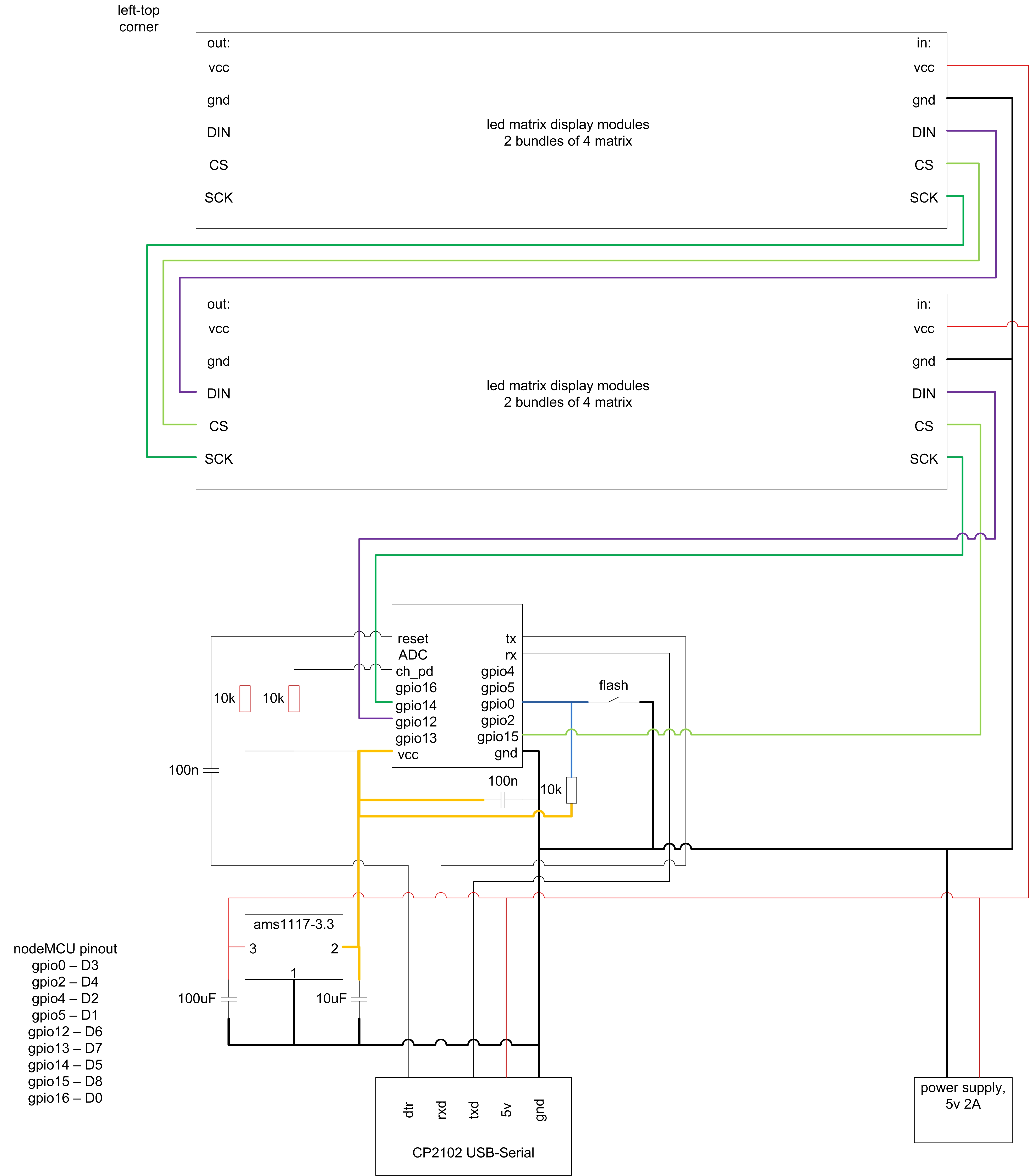
The schematics is shown on the picture below. The left-top matrix is the last in the sequence, then the SPI bus goes right to right-top corner (8 matrices in line) then the bus goes to the left-bottom matrix and finishes on the right-bottom corner of the display. The controller is connected to the right-bottom matrix.
The power lines (vcc+gnd) can be connected to the matrices in any order. Make sure you connect the power to each matrix module using good-quality wires.
As you can see from the schematics, the 3.3 voltage source is connected to the micro controller only. Surely, we have a signal level of 3.3 volts on SPI bus, but the matrices are working properly in this case.
All the matrices is powered by 5 volts. The display required 1-2A power supply to work properly.
The cascaded matrices are managed by loading a 16-bytes sequence via SPI bus at once. The first byte in the sequence will be loaded to the top-left matrix, the 16-th byte - to the bottom-right one. The controller redraws the display in less than 1 ms.
The main challenge of the display were the fonts. We need some font to draw the text! As soon as true type font is a cpu hangry to be implemented we need a raster font to use. After searching the Internet I have remembered the great graphic library, u8lib, distributed with a huge amount of the fonts and implemented some procedures to display these fonts on the display.
The sketch is using several Cyrillic win1251 fonts from the u8gib library and converts the text from utf8 encoding to the win1251 one-byte font. You can use any other font in this display if you wish. The ASCII encoding should work perfectly. As to national symbols, the corresponding decode procedure should be implemented.
The display can be increased in size I believe. The main point is to build it line-by-line with the matrix modules. The sketch allocates the memory for the display dynamically depending on the size of the display.
If you have built the different size display, the parameters in the constructor should be changed.


Comments