Do you have a watercooling system for your PC? Do you enjoy nerding things out and making them as good as possible? This project might be for you. Is it an overkill? Yes. Is it a perfectionist dream in terms of precise monitoring and control of your watercooling? Probably quite close. Even if you don't have watercooling, you might find it useful, just using some snippets of my code to make a fan controller for something else or whatnot. In this essay, I am going to not only explain the project itself, but also all that I learned along the way to making it a reality, as I've seen people struggling with these solutions on the internet, so I hope it will be useful for you, either in its entirety, or at least parts of it!
TL/DRThe project involves the following functionality:
- Stabilizing the water temperature at the given level by adjusting the fan speed
- Stabilizing the difference between hot and cold water by the pump speed
- LCD monitoring of NVidia GPU core and VRAM temperatures
- Automatic detection if a crypto mining app is running on the PC to set the operating mode accordingly
- LCD backlight toggle by a press of a button (for example, use the PC Reset button)
- LCD backlight toggle by running a program on the PC (for example, bound to a keyboard hotkey)
I have a PC with an RTX3090 in it, watercooled with a double sandwich waterblock from EKWB. I stood in front of a challenge: how to control the watercooling. The problem is, in the BIOS, there is no option for controlling the fans and pump based on GPU's temperatures. So I figured, cooling based on the water temperature should do the trick. Happily, my motherboard has one header for an external 10k thermistor-type NTC temperature sensor AND there are such sensors available for putting in-line with your watercooling loop, at any place you'd like - I chose Alphacool Icicle temperature sensor and I put it at the "cold water" location, where the water exits the radiator and goes to the graphics card, as this one determines the cooling capacity. I set a fan curve to respond to the water temperature and... I ended up disappointed. The temperature read resolution is only 1°C and I found out that to keep the watercooling system reasonably responsive, the fan curve had to be quite sharp. This resulted in the fans ramping up and down annoyingly when the water temp read jumped from 40.0°C to 41.0°C or to 39.0°C. I didn't want it like this. So I turned to external fan control and monitoring project with Arduino, as I wanted to learn Arduino at some point anyway!
Possibly you can work out a great watercooling control using a software solution, that JayZTwoCents talked about.
https://github.com/rem0o/fancontrol.releases
With this, you can drive the water cooling system based on GPU temps. It does not have GPU VRAM temperature readout by default (temps get toasty on RTX3090 so it's pretty crucial IMO...), but I heard there is a plugin that "grabs" sensor data from HWinfo - google that if you are interested. Nonetheless, I was already dedicated to come up with my own hardware solution, so here it comes!
Theory of smart watercoolingI began with physics calculations of the watercooling - I am a physicist so it was fun for me to figure this out. I am not going to bore you with details of the physics, so just the crucial information I found out:
- Temperature difference ΔT between the hot and cold water in the loop is solely determined by the GPU power and the water flow rate. Too high flow rate makes the ΔT smaller, and smaller ΔT does not necessarily improve the cooling efficiency. It makes sense to drive the waterpump at just the right speed, to maximize the cooling efficiency and increase the longevity of the pump. The trick is to keep the ΔT constant at a reasonable level. About 2°C of ΔT is what I estimated works best for the cooling efficiency. This effectively means that the hottest VRAM die on your GPU will be 72°C and the coldest 70°C, for example.
- Once you have the pump speed set based on the ΔT, the only variable to control left is the speed of the fans, and they effectively determine the water temperature. The water temperature in the steady state equilibrates based on the current GPU power and the fan speed, given the pump speed set in the previous step. So, setting the fan speed to keep the water temp constant gives a consistent cooling performance!
As we need the ΔT, a second sensor is needed and this one I installed at the hot-water location - where the water heated by GPU enters the radiator.
I2C accessoriesPre-note for this paragraph: I hardcoded the addresses of the I2C devices as I determined them using the I2C scanner Arduino sketch. If you encounter some not-working I2C device, it might have a different address, so to make sure you have the addresses right, use an I2C scanner Arduino program like this one: https://create.arduino.cc/projecthub/abdularbi17/how-to-scan-i2c-address-in-arduino-eaadda
PWM FAN CONTROL 25kHz
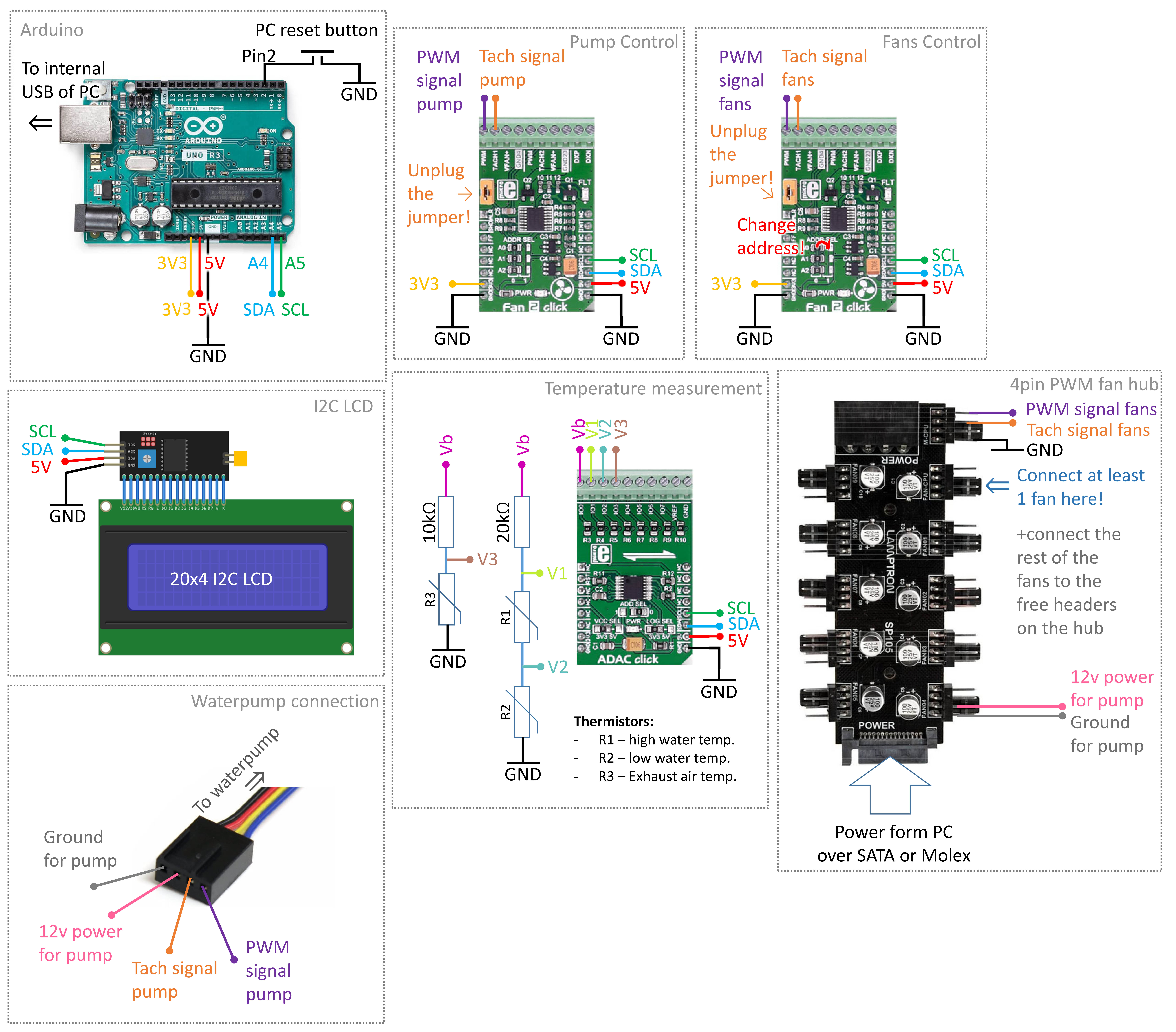
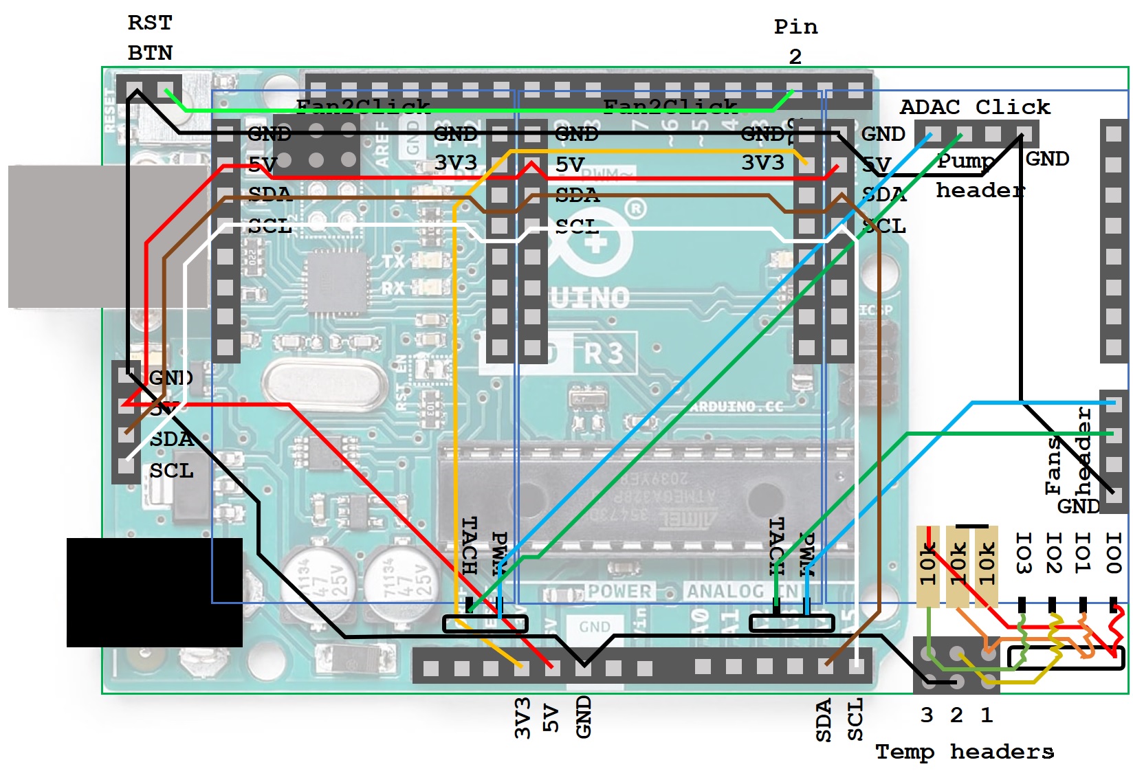
OK. Now we come to the Arduino side of things. I stumbled upon some Arduino projects for controlling PWM fans, but they mostly required taking over the timers for synthesizing the 25kHz PWM signal necessary to control the fans or pumps, and I preferred to avoid that, as I did not know if that wasn't going to cripple any other functionality I would potentially want the Arduino to perform. There is a library FanController (https://github.com/GiorgioAresu/FanController), but I wasn't quite sure it creates a 25kHz signal, and this is important for PWM fans. Moreover, synthesizing 2 independent PWM signals appeared even more tricky. So, instead, I found out about the fan controller IC MAX31760, interfaced over I2C protocol with Arduino. Microe makes development boards Fan2Click with these ICs onboard, convenient in usage in prototypes like mine! I got 2 of them, one for the pump, one for the fans. As it goes with using multiple identical devices on the same I2C bus, you need to make sure they have a different addresses, so they can be addressed independently. In order to do that, I took the 2nd Fan2Click, desoldered one address jumper from the 0 position, and soldered it back onto the 1 position as in picture below. Also, remove the jumper on both Fan2Clicks, to enable 4pin fan -compatible operation!
There appeared an obstacle - I could not find open-source Arduino libraries for this chip, so I had to create my own functions: from the basic ones like sending/reading a byte from a particular address in the memory up to functions like "set fan speed to X" and "read tachometer". I had some fun with the datasheet of MAX31760 and learned the I2C protocol workings ins-and-outs, and wrote my code appropriately.
10bitADC/DAC and analog temperature measurement
For the analog temperature readout, I could not find a dedicated I2C chip for this purpose, so I decided to create a simple voltage divider and use a generic 10bit ADC/DAC offered by Microe too, it's called ADAC Click and it has an AD5593R chip on board (this starts sounding like an ad for Microe, but hey, one provider - one shipping!). Why did I not use Arduino's in-built ADC/DAC? A few things:
- DAC works in PWM mode on Arduino and not on a stable voltage. I could have used the high 5V output for biasing a voltage divider, but I found this might be too much for the 10k thermistors. I wasn't sure, but I preferred to be on the safe side.
- ADC on Arduino is "only" 8-bit. Might be fine for most applications, but if you need a 0.1°C precision, you better go with a 10bit in this application.
Luckily, AD5593R has libraries for Arduino (https://github.com/LukasJanavicius/AD5593R-Arduino-ESP32-Library) so it was super easy to implement. Just make sure, before installing the library, to comment the line 31 in the AD5593R.h which says "#define AD5593R_DEBUG". If you don't do that, the debugging constantly sends read and set voltages via the serial bus and keeps it busy - you don't want that unless you're actually debugging.
The measurement of temperature is relatively simple. You can treat the 10k thermistors basically as resistors, whose resistances depend on their temperature. So, once you measure the resistance, you just need to convert the resistance to temperature. To measure the resistances, I implemented simple voltage dividers (see: wiring diagram in the further part). Then, to convert resistance to temperature, I used values from the table: https://www.yumpu.com/en/document/view/37022739/10k-2-thermistor-output-table-10k-2-thermistor-output-table-bapi
I took the values and used the physics of a thermistor. The resistance R of the thermistor depends exponentially on the temperature, following equation 1, where r_∞ is the hypothetical resistance at infinite temperature, E_A is so-called activation energy, k_B is the Boltzmann's constant. Equation 1 can be transformed into equation 2 - you just need to establish the values of A and B, which I've done by fitting the equation 2 to the data from the table mentioned above and I got A= 2.5490E-4 and B = 1.0062E-3. Note: "log" is the natural logarithm. Just remember, this way you get the temperature T in Kelvin, so just subtract 273.15K form the result and you get the temperature in °C!
I2C LCD
I also wanted an LCD monitor, and I used the known and loved 20x4 LCD with an I2C backpack. For toggling the backlight, I wired the reset button of the PC to shorten down to the ground a pulled-up input pin of the Arduino. At last, a good use for this button, never even pressed before! For using I2C LCD, make sure to install the library https://github.com/fdebrabander/Arduino-LiquidCrystal-I2C-library
Preparing Python for communication with ArduinoLast, but not least, I included the GPU CORE and VRAM temperature monitoring. This was more tricky than I anticipated, but I found the way, which I am going to explain for my particular case - should work for modern generations of nVidia GPUs, as long as you have latest drivers. I'll describe it for my case as I use MS Windows 10 OS.
- The first thing you need is to install python3 on your PC: https://www.python.org/downloads/
- Install PIP, a package installer: https://phoenixnap.com/kb/install-pip-windows
- Enter pip install pynvraw in the command line to install the pynvraw package - this is for accessing GPU's information programatically.
- As you're on it, do the same for other the packages needed for the python program that I will show later: pip install X, where X is serial, time and psutil, one by one. Serial is for the serial communication with Arduino, time is for timing and delays, psutil is for checking the running processes (you will see just below where it becomes important).
Another functionality I wanted was to toggle the LCD backlight with a keyboard shortcut, besides of just the reset button, as mentioned before. This appeared as a bit of a hurdle, because when one program has already open COM port to Arduino over USB, another program cannot open it! So the solution was to open the port in a loop in a 0.5s interval to send the GPU data to Arduino and close it right away, so that the LCD backlight toggle program can wait for its turn. This approach generated another problem: opening a COM port to Arduino normally resets the Arduino! I did not want that. The solution was to disable the DTR- you see it in my python code. With DTR disabled, opening the port sends some rubbish bytes to Arduino first, before sending the actual data, so I had to read the rubbish bytes out on the Arduino side, until a "data begins byte" was found (in my case, a - spacebar character).
Custom temperature encoding and crypto-miner detection
To keep the port open for as short as possible for a smooth operation, I decided to "encode" or "compress" the data. The data was: GPU CORE temp at a 0.1°C precision (for example 54.1°C) and the VRAM temp at a 1°C precision (for example 68°C). So, if you send the data as a string, you need at least 3 bytes for the CORE if you multiply by 10 and round to an integer (for example 541) and 2 bytes for the VRAM (for example 68). Instead, I encoded the numbers as integers in the base 94 and sent them as chars of a string, offset by 33 (char 33 is a "!"). I chose the offset of 33 to keep the chars from 0 to 32 as control bytes that I might use in the future for improvements to my project. I know this is convoluted, but it allowed me to use only 2 bytes for CORE temp and 1 byte for the VRAM temp information. You can see my approach to encode it in my python code, and how to decode it in the Arduino program.
I also use the PC for crypto mining on the side with nicehash to make a few bucks back from my investment in the PC 😅. Mining requires a bit more strict cooling than gaming (lower water temp target). In the python code, there is a function that detects if the process "excavator" is running, and sets the final byte to send to Arduino as Y (yes, it's running) or N (no, it's not running). It was important to set in Arduino the "mining mode" as default if no data is received from the serial, because better to have stronger cooling in case the python crashes for some reason.
In summary, the bytes I send from the python are, in sequence: [spacebar][CORE byte 1][CORE byte 2][VRAM byte][Is excavator open Y/N].
The LCD backlight toggle was a much simpler python program that just sends a spacebar and a tabulator \t (char 9). I bound the program to a keyboard shortcut.
Algorithm to adjust the PWM of pump and fansI didn't bother converting PWM to a percentage scale - I preferred to keep it as a byte integer from 0 to 255, 255 meaning 100% PWM. My approach was to create a kind of "thermostat" - to define how much to change the PWM in the loop iteration based on how big is the deviation of the actual temperature from the set temp target. This is the function changePWM(int num, float Temp, float TempSetPoint) in my Arduino code. num is the fan controller number (1 - pump, 2 - fans), Temp is the measured temperature, TempSetPoint is the temp setpoint, self-explanatory. To control the pump, as mentioned earlier, the temperature argument is the difference between hot and cold water. For the fans, the argument is the cold water temperature.
The algorithm stands as an integer linear function:
int deltaPWM = (Temp-TempSetPoint)*PWM_SLOPE;
and then, if the computed deltaPWM is outside the range of +/- PWM_DELTA_MAX, put it at the respective range limit. The PWM_SLOPE decides how sharply the algorithm reacts to the temp deviations. Then, the PWM is changed by the deltaPWM up to the max of 255 or down to the min of 0.
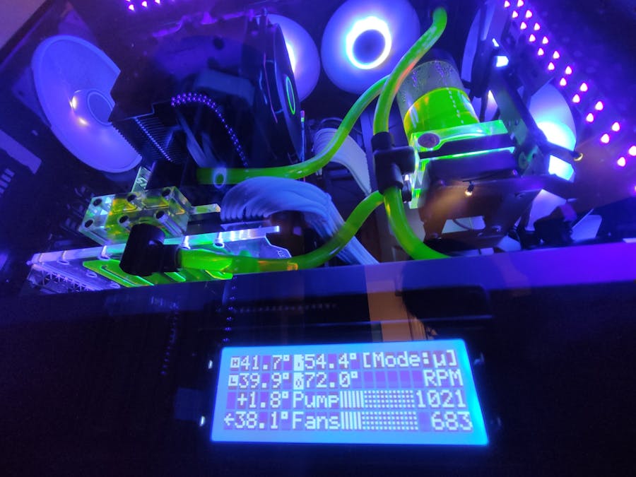
I came up with a seamless bar graphing of the current PWM of pump and fans. The challenge was that there are 1px wide gaps between the characters on the I2C LCD. So, I decided to make a graph of 3 lines per char, with a dotted background, which looks like this on my LCD:
It required only 4 custom characters to define: 0, 1, 2 and 3 bars. The function displayPWMChart does the trick. You can figure out how the function works mostly; the thing that requires an explanation is how to calculate the number of bars to display. It is done by the integer calculation int bars = (pwm+7)*18/255;. The number 18 comes form the total number of bars I have (6 char wide graph x 3 bars per char), 255 is the max value of PWM, and the offset of 7 I chose to mimic the "rounding" as if this was a floating point calculation, not an integer one - this is just for computation efficiency.
I can foresee a few ways of improvement. The first thing would be to design and fabricate an actual PCB to connect everything together instead of 3D printing and wiring everything by hand. One could even completely design a PCB with the Atmega 328p microcontroller (the one that Arduino has) and the ICs from the click boards (AD5593R-theADC/DAC, and MAX31760 - the fan controller) and wire everything neatly with all the necessary passive components on one, tiny PCB - this would be a great way of miniaturisation of the project! One could experiment with other displays as well. I was also thinking of wiring the tach signals to the PC motherboard fan headers so that the PC can read the pump/fan speeds too, but I am not sure if it would be as simple as just making a splitter that and I didn't want to risk that. It also wouldn't hurt to add another thermal probe to monitor the temperature inside the PC case.
Summary and photos of the projectI had a lot of fun with this project, learning Arduino by doing something actually useful! I am sure there are a lot of ways it can be improved, and I welcome all the feedback you might have. I am by no means a master programmer, nor an electronics expert, so surely the code or wiring is not up to highest standards. But it works great! If you'd like to get any explanation from me or give/get advice, please don't hesitate to reach out.


_ztBMuBhMHo.jpg?auto=compress%2Cformat&w=48&h=48&fit=fill&bg=ffffff)


Comments