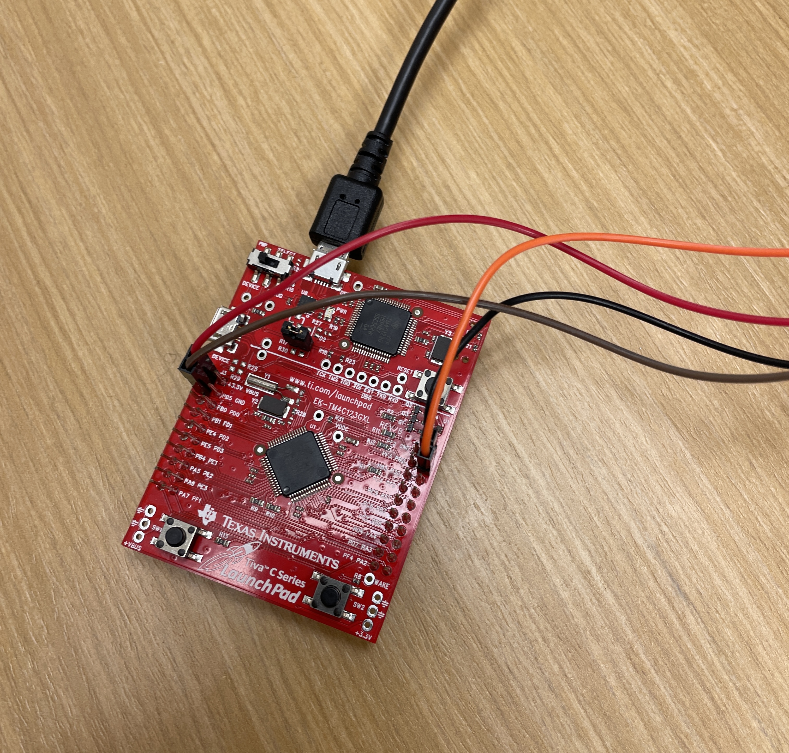
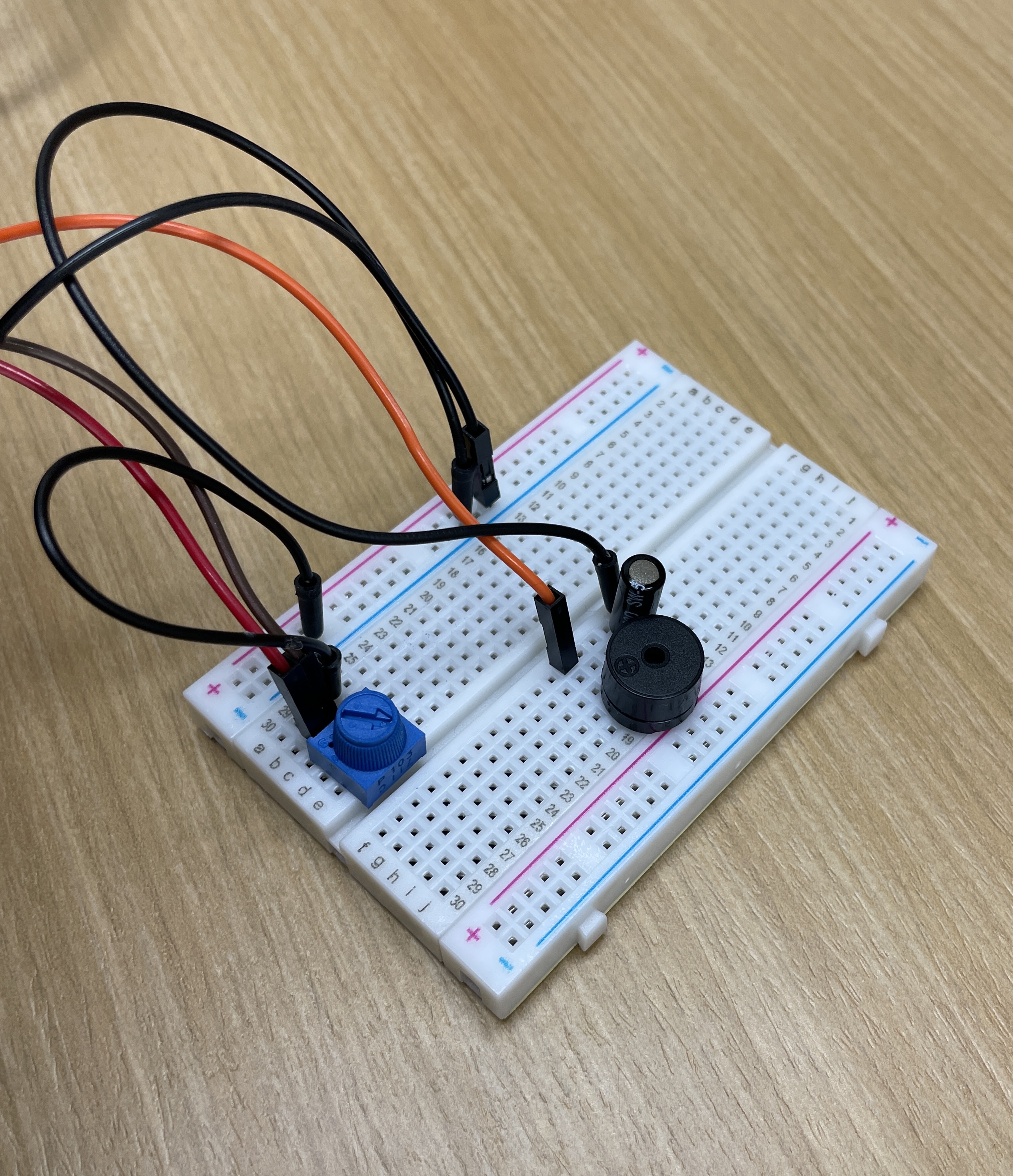
Navid GhodsiAdam SwartzEric LiuRyan Ramos
Published © GPL3+

DJ Khable

Fun and easy-to-use speaker that lets you make music with the turn of a knob!

IntermediateFull instructions provided3 hours67
DJ Khable

Things used in this project

Hardware components

EK-TM4C123GXL TM4C Tiva LaunchPad
Texas Instruments EK-TM4C123GXL TM4C Tiva LaunchPad
×1
Buzzer, Piezo
Buzzer, Piezo
×1
Single Turn Potentiometer- 10k ohms
×1
Breadboard (generic)
×1
Jumper wires (generic)
×6
Tilt Switch, SPST
Tilt Switch, SPST
×1

Software apps and online services

Energia
Texas Instruments Energia

Story

Read more

Schematics

Schematic

LaunchPad

Breadboard

Video Demo

Code

Code

C/C++
/*
  Example 06: Potentiometer (Variable Resistor)
  Sidekick Basic Kit for TI LaunchPad

  We will use a variable resistor called a potentiometer
  (or pot for short) that uses a mechanical knob to
  change the resistance. We can also use the buzzer and/or
  LED on the LaunchPad to let us know when we pass a threshold.

  Hardware Required:
  * TI LaunchPad
  * Breadboard BoosterPack
  * Breadboard
  * Potentiometer
  * 5x Jumper wires
  * Buzzer

  This example code is in the public domain.
*/

// define your pitch constants for the buzzer
#define NOTE_B0  31
#define NOTE_C1  33
#define NOTE_CS1 35
#define NOTE_D1  37
#define NOTE_DS1 39
#define NOTE_E1  41
#define NOTE_F1  44
#define NOTE_FS1 46
#define NOTE_G1  49
#define NOTE_GS1 52
#define NOTE_A1  55
#define NOTE_AS1 58
#define NOTE_B1  62
#define NOTE_C2  65
#define NOTE_CS2 69
#define NOTE_D2  73
#define NOTE_DS2 78
#define NOTE_E2  82
#define NOTE_F2  87
#define NOTE_FS2 93
#define NOTE_G2  98
#define NOTE_GS2 104
#define NOTE_A2  110
#define NOTE_AS2 117
#define NOTE_B2  123
#define NOTE_C3  131
#define NOTE_CS3 139
#define NOTE_D3  147
#define NOTE_DS3 156
#define NOTE_E3  165
#define NOTE_F3  175
#define NOTE_FS3 185
#define NOTE_G3  196
#define NOTE_GS3 208
#define NOTE_A3  220
#define NOTE_AS3 233
#define NOTE_B3  247
#define NOTE_C4  262
#define NOTE_CS4 277
#define NOTE_D4  294
#define NOTE_DS4 311
#define NOTE_E4  330
#define NOTE_F4  349
#define NOTE_FS4 370
#define NOTE_G4  392
#define NOTE_GS4 415
#define NOTE_A4  440
#define NOTE_AS4 466
#define NOTE_B4  494
#define NOTE_C5  523
#define NOTE_CS5 554
#define NOTE_D5  587
#define NOTE_DS5 622
#define NOTE_E5  659
#define NOTE_F5  698
#define NOTE_FS5 740
#define NOTE_G5  784
#define NOTE_GS5 831
#define NOTE_A5  880
#define NOTE_AS5 932
#define NOTE_B5  988
#define NOTE_C6  1047
#define NOTE_CS6 1109
#define NOTE_D6  1175
#define NOTE_DS6 1245
#define NOTE_E6  1319
#define NOTE_F6  1397
#define NOTE_FS6 1480
#define NOTE_G6  1568
#define NOTE_GS6 1661
#define NOTE_A6  1760
#define NOTE_AS6 1865
#define NOTE_B6  1976
#define NOTE_C7  2093
#define NOTE_CS7 2217
#define NOTE_D7  2349
#define NOTE_DS7 2489
#define NOTE_E7  2637
#define NOTE_F7  2794
#define NOTE_FS7 2960
#define NOTE_G7  3136
#define NOTE_GS7 3322
#define NOTE_A7  3520
#define NOTE_AS7 3729
#define NOTE_B7  3951
#define NOTE_C8  4186
#define NOTE_CS8 4435
#define NOTE_D8  4699
#define NOTE_DS8 4978

// notes for a D major scale
int notes[8] = {NOTE_D4, NOTE_E4, NOTE_FS4, NOTE_G4, NOTE_A4, NOTE_B4, NOTE_CS5, NOTE_D5};
// button that will be used to switch between states
const int buttonPin = PUSH2;
const int ledPin =  GREEN_LED;
// used to make the button a toggle
bool wasPressed = false;
int prevState = 0;

int buttonState = 0; 

/* In the setup function we will set our LED and buzzer as
 * OUTPUT. You can change the LED or buzzer pin to match
 * your cicuit.
 */
void setup()
{
  // Connect potentiometer wiper (middle pin) to analog pin 2
  // Connect the left and right pins to VCC and GND
  // Connect the buzzer longer leg to pin 19 and shorter leg
  // to GND
  // Note: we don't have to configure analog pins as input or
  // output to use them
  Serial.begin(9600);
  
  pinMode(RED_LED, OUTPUT);  // set your LED pin to OUTPUT
  pinMode(19, OUTPUT); // set your Buzzer pin to OUTPUT
  tone(19,NOTE_C6);
  noTone(19);

  // initialize the LED pin as an output:     
  // initialize the pushbutton pin as an input:
  pinMode(buttonPin, INPUT_PULLUP);   
  
}

/* In the loop section we will read potentiometer pin. If
 * it crosses the threshold then we will turn on the LED
 * and play a tone with the buzzer. If it goes below the
 * threshold then the LED and buzzer turn off.
 */
void loop()
{
  //Serial.print("loop begin");
  int analogValue; // create a variable to store the analog reading
  analogValue = analogRead(2); // store the analog reading

  // get the reading from button
  buttonState = digitalRead(buttonPin);

  if(buttonState != HIGH && wasPressed) {
    // don't do anything
  }
  else if(wasPressed) {
    wasPressed = false; // wasn't pressed before, so set wasPressed to false
  }
  if(buttonState != HIGH && !wasPressed) {
    // button was recently pressed, so switch state and set wasPressed to true
    prevState += 1;
    prevState %= 2;
    wasPressed = true;
  }

  if(prevState == 0) { // discrete state, plays the notes of a scale as the knob is turned
    int noteIndex = analogValue/512;
    tone(19, notes[noteIndex]);
    // switch lights to indicate what state we are in
    digitalWrite(RED_LED, LOW);
    digitalWrite(GREEN_LED, HIGH);
  }
  else { // continuous state, doesn't play a specific note but maps to a certain pitch
    tone(19, analogValue);
    // switch lights to indicate what state we are in
    digitalWrite(GREEN_LED, LOW);
    digitalWrite(RED_LED, HIGH);
  }
  pinMode(ledPin, OUTPUT);
  // this delay sounded the best (for smoothness), but anywhere between 5 and 50 sounds okay
  delay(20);
  // turn off buzzer
  noTone(19);
}

Credits

Navid Ghodsi

Navid Ghodsi

1 project • 0 followers
Adam Swartz

Adam Swartz

1 project • 0 followers
Eric Liu

Eric Liu

1 project • 0 followers
Ryan Ramos

Ryan Ramos

1 project • 0 followers
Thanks to Energia.

Comments