


Hardware components | ||||||
| × | 1 | ||||
 |
| × | 1 | |||
 |
| × | 1 | |||
 |
| × | 1 | |||
 |
| × | 1 | |||
Software apps and online services | ||||||
| ||||||
| ||||||
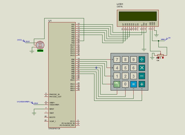
The servo motor is one of the key components in many electronics projects, especially those that require precise movement, such as robotic arms or simple mechanical systems. However, in practice, adjusting the servo angle is often done using a potentiometer or software connected to a comput. this methods that are less practical for direct, on-site use. This led us to the idea of creating a tool that allows users to set the servo angle directly using a keypad for input and an LCD to display the entered angle.
We developed this project as a way to explore simple input systems that can operate independently without relying on a computer. By using only a microcontroller, a keypad, and an LCD, users can simply enter the desired angle, and the servo will move accordingly. This process not only simplifies usage but also offers an engaging learning experience about how to handle digital input and convert it into precise mechanical motion.
Compared to other, more complex projects, this one offers high practical value. It is not only suitable for experimentation but can also be applied directly in various real-world scenarios. While it may seem simple, this approach provides a strong foundation for understanding the interaction between input, processing, and actuation in electronic systems.
Short description of program code
1. Initialization and basic configuration
This program is intended for the STM32F401, utilizing register and standard C libraries such as stm32f401xc.h and string.h to control the device. The LCD and servo pins are configured at the beginning, and the servo angle input is stored in a buffer. The delay_ms() function provides delays using SysTick, while SystemClock_Config() sets the system clock via the PLL for faster and more stable performance.
2. Initialization GPIO
The GPIO_Init() function enables the clock for GPIOA and GPIOB ports, then configures the GPIOA pins for LCD communication and servo control. The configuration includes output mode, push-pull type, high speed, and alternate function settings for the servo pin. GPIOB is also configured for additional input/output purposes, including mode selection, pull-up/pull-down settings, and high speed. This entire initialization ensures that the pins operate according to their roles for the LCD, servo, and other communication tasks.
3. LCD function
This program controls a 16x2 LCD in 4-bit mode using a microcontroller and direct access to GPIO registers. The lcd_pulse() function sends a signal to the LCD's EN pin, while lcd_nibble() transmits 4-bit data to the LCD. The lcd_send() function sends 8-bit data by splitting it into two nibbles. lcd_init() initializes the LCD, lcd_clear() clears the display, lcd_set_cursor() sets the cursor position, and lcd_puts() displays text. These functions enable the microcontroller to efficiently display data on the LCD.
4. Servo control function
This code snippet is used to control the rotation angle of a servo motor using PWM from the TIM1 timer on the microcontroller. The set_servo_angle() function takes an angle value between 0–180 degrees and converts it into a corresponding compare register value (ccr_value) that matches the PWM pulse, then sets the CCR1 register to adjust the servo position. The TIM1_Init() function initializes the TIM1 timer to generate a PWM signal with a 20 ms period (50 Hz frequency), configures the PWM mode, and enables output on channel 1. After initialization, the servo is set to an initial angle of 0 degrees.
5. keypad function
This code snippet is used to read input from a 4x3 keypad. The keypad_map matrix contains the arrangement of characters according to the button positions on the keypad. The scan_keypad() function scans each column one by one by setting it to a low logic level and reading the rows to detect a pressed key. If a key press is detected, the function returns the corresponding character from the keypad_map; if no key is pressed, it returns zero (0).
6. main function
This code sets up a keypad input system and servo angle control using the STM32. When a button is pressed, the scan_keypad() function detects the character from the 4x4 keypad and displays it on the LCD. If the ‘*’ button is pressed, the user is prompted to enter an angle, and if the ‘#’ button is pressed, the entered value is converted into an angle and the servo is adjusted accordingly. The set_servo_angle() function converts the angle value into a PWM signal using the TIM1 timer, which has been configured to match the servo signal period.


Comments