


Hardware components | ||||||
_ztBMuBhMHo.jpg?auto=compress%2Cformat&w=48&h=48&fit=fill&bg=ffffff) |
| × | 1 | |||
_wzec989qrF.jpg?auto=compress%2Cformat&w=48&h=48&fit=fill&bg=ffffff) |
| × | 1 | |||
 |
| × | 1 | |||
 |
| × | 1 | |||
 |
| × | 1 | |||
 |
| × | 1 | |||
| × | 1 | ||||
 |
| × | 1 | |||
 |
| × | 1 | |||
Software apps and online services | ||||||
 |
| |||||
A well know home automation system provider uses the BlueBus Technology to connect its sensors (pair of photocells...) to the Controlling Unit. Let's re-use these sensors for any kind of Arduino project.
The challenge is to get the Arduino behave like the controlling unit and be able to get the status of the sensors.
The BlueBus is made of only a pair of 2 wires, all sensors are plugged in derivation on these 2 wires. This is both the power supply and the communication media.
I haven't found any useful documentation on the Internet, describing the type of electric signal and transmission protocole for this bus. No problem, let's investigate...
For the time being, this project is just a proof-of-concept.
Bus conceptsThe bus shows a 12V DC voltage which is used to power the devices connected (typically a pair of TX and RX photocells).
It allows as well a bidirectional communication between the controlling unit and the devices by modulating voltage and current with pulses.
Communication from controlling unit to devices: every 32ms, the controlling unit shut down the power supply of the bus for short time pulses, building a 8-bit message. This message is mainly the address code of one of the connected devices. These pulses are received by all the devices, only the addressed device should then reply to the controller.
Communication from a device to the controlling unit: the addressed device start to reply immediately after the end of the controlling unit message. It uses the same type of pulses to form a 8-bit reply message. But in this case, these pulses do not change the voltage but the current circulating in the bus. Each pulse causes the current to increase to about 160mA. The controlling unit monitor the current consumption on the bus and can get the reply message.
The base frequency for sending bits is 600Hz, meaning about 1.66ms per bit. This duration is split in 3 thirds where each bit is coded as a sequence of a LOW level and a HIGH level:
                      _0.56_
bit "1"  |___1.1ms___|      |
                 ___1.1ms___
bit "0"  |_0.56_|           |
the full message is made of 8 bits of data (MSB first) + 1 stop bit (0):
 |------------32ms-------------|      xxxxxxxx: message from ctrlling unit
 |xxxxxxxx0-------16.9ms-------|      yyyyyyyy: message from device
 |xxxxxxxx0yyyyyyyy0---1.8ms---|      0 are the stop bits
The sequence question/reply is repeated every 32ms.
During a recognition phase, the controlling unit queries each of the possible address codes of devices, listen for a reply (if any) and build a list of connected devices on the bus. Then, it queries each of these devices, one after the other, and gets their replies.
Message from Controlling Unit to Devices : aabcccfp
     aa : address extension (0 ?)
     b  : address modifier (A bridge on the board)
     ccc : addr as configured with the jumpers
     f : reset flag ? should be 1 for normal operation
     p : parity bit
Devices have jumpers on their board where their address code can be configured, from 1 (ccc=001) to 15 (ccc=111).
The reply message is somehow scrambled in order to detect any collision (2 devices having the same address on the bus):
Reply mmessage from Devices : xxxxyyyy
     xxxx xor yyyy xor bccc --> effective data (4 bits)
(bccc is the address code of the device + its address modifier)
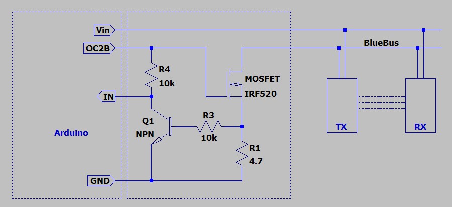
In order to let the Arduino send the messages (acting as the Bus Controlling Unit) and read the reply from the devices, a very small piece of hardware is required.
Vin  : 12V supply from the Arduino (using a DC adapter)
OC2B : output from Arduino,
        - when LOW : MOSFET is blocked, power is cut on the bus
        - when HIGH: MOSFET is conducting, bus is powered with Vin
IN   : input of Arduino for reading the replies
        - when device increase the current to 160mA, the voltage on
          the 4.7ohm resistor is enough to activate the transistor
          and pull down the IN line to GND
        - when device is in standby, current is quite low, transistor is
          blocked, the IN line is pulled up to Vcc (5V) coming
          from the OC2B line
As a consequence, the IN line is showing both the sent message (available on OC2B) and the reply.
The software intensively uses the integrated TIMER/COUNTER of the Arduino processor to generate the desired waveform and the interrupt mechanism.
The 8-bit timer TIMER2/COUNTER2 is used, setup in the fast-PWM mode, and using the OC2B output signal available on pin D3 (UNO) or D9 (MEGA):
* The input clock for TIMER2 is set as CPU clock divided by 128, giving
  a 8µs time interval
* TCNT counter is incremented every 8µs and is reset when reaching the
  value in register OCRA, set to 210:
    210 * 8µs -> 1.68ms, duration of 1 bit
* When counter resets, the OC2B output is set to LOW.
* OCR2B is set to either 210/3 (for a "0" bit) or 210*2/3 (for a "1" bit)
* at the time TCNT counter reaches OCR2B value, after 0.56ms or 1.1ms
   o the OC2B output is set to HIGH
   o an interupt is generated and the ISR routine sets the next value
     for the OCR2B register
When no data is to be sent, the OC2B output is disconnected from the pin, the signal available on the pin is then basically a normal digial output.
The ISR routine is also used for reading the reply from the IN pin.
* OCR2B is set to 210/2 (right at the middle of the bit)
* interrupt calls ISR at this time
* ISR read the status of the IN pin and decide if the bit is "0" or "1"
time scale in...    ms             number of 8µs ticks
                        _0.56_                 __70__
bit "1"    |___1.1ms___|      |     |___140___|      |
                    ^                        ^
                   ___1.1ms___              ___140___
bit "0"    |_0.56_|           |     |__70__|         |
                    ^                        ^
interrupt here    __|                      __|
The source file is well commented, many additional information available there.
To be really easy-to-use, the code provides simple functions (all names are prefixed with "BB_"). They can be easily called by a real application program. A typical application could be:
... insert here the library code, or #include it ...
void setup() {
 BB_init(3);       // read bus on port D3
 BB_on();          // activate bus and communication
 delay(1000);      // wait for the devices to power-up
 BB_recognition(); // initiate a recognition phase
}
void loop() {
 BB_Event* e;
 while ((e=BB_event_pop())->evt) {
   Serial.print("Device ");
   Serial.print(e->addr, HEX);
   Serial.print(", new status ");
   Serial.print(e->status, HEX);
   Serial.print(", timestamp ");
   Serial.println(e->timestamp);
 }
 delay(200);
}
Yes, Arduino can act as a BlueBus controlling Unit and gets the status of the photocells or sensors connected!


Comments