

Hardware components | ||||||
_ztBMuBhMHo.jpg?auto=compress%2Cformat&w=48&h=48&fit=fill&bg=ffffff) |
| × | 1 | |||
| × | 1 | ||||
| × | 2 | ||||
| × | 2 | ||||
| × | 17 | ||||
| × | 2 | ||||
| × | 1 | ||||
 |
| × | 4 | |||
| × | 4 | ||||
| × | 1 | ||||
| × | 1 | ||||
| × | 24 | ||||
| × | 1 | ||||
| × | 1 | ||||
Hand tools and fabrication machines | ||||||
 |
| |||||
| ||||||
| ||||||
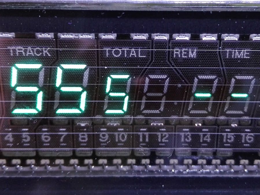
VFD displays are not trending anymore for some obvious reasons, they are made of glass ("uh cool!"), have an incandescent filament ("really??"), they are basically vacuum tubes ("interesting!"), they make a light so brilliant, sometimes colored, it needs a dark plastic on top ("uh, cool again!").
Usually you need a dedicated chip to drive em, most modules/appliances come with this chip that you can control independently via I2C or SPI (that is way better in terms of ease), in case you buy or have one of those displays and lack such chip it's not so easy to "connect and go," the ideal would be buying that chip (that comes in SMD format usually). This circuit gives a pretty decent interface for like an Arduino and can drive quite likely any VFD, including the bulky "tube" vintage ones, but matrix displays with a lot of segments are not a good idea by the way, you can expand the circuit but THOUSANDS... mhhh, maybe not.
Pros and ConsPros
- almost zero cost (hopefully)
- easy to find parts
- high voltage capability (up to hundreds Volts on the anodes)
- independent grids and anodes voltages
- only 3 digital data lines needed
- expandable (it requires more CPU work in case)
- code is ready made for every 8-bit Arduino
Cons
- requires a bunch of different voltages and supplies (not weird for VFDs)
- no dimming function (except from voltage drive)
- uses two Arduino resources, the SPI and timer1
- you can't hang the microcontroller, otherwise the scan freezes on a grid
- it's not a pair of resistors and Leds, it requires a bit of work
A VFD usually works in a multiplexed fashion, like a 2D matrix with X and Y axis, you need to heat up the filament (the cathode, you see those thin wires in front of it), connect the ground on that filament as well, a positive voltage to a grid (control grid, one point of the X axis) and again a positive voltage on a segment pin (the anode, one point of the Y axis), at this point a segment (just one) lights up. To light up whatever segment and whatever combination, and having "few" wires around, the multiplexing selects one grid per time and at the same time configures the anodes to light up the corresponding segments under that grid, a moment after, it selects another grid and configures the anodes this time for having the corresponding segments correctly lighted up under that second grid. Speeding up this continuous repeating scan results in a movement so fast that under our eyes it doesn't select one grid per time, but looks driven at once, this is the so called POV (Persistence Of Vision).
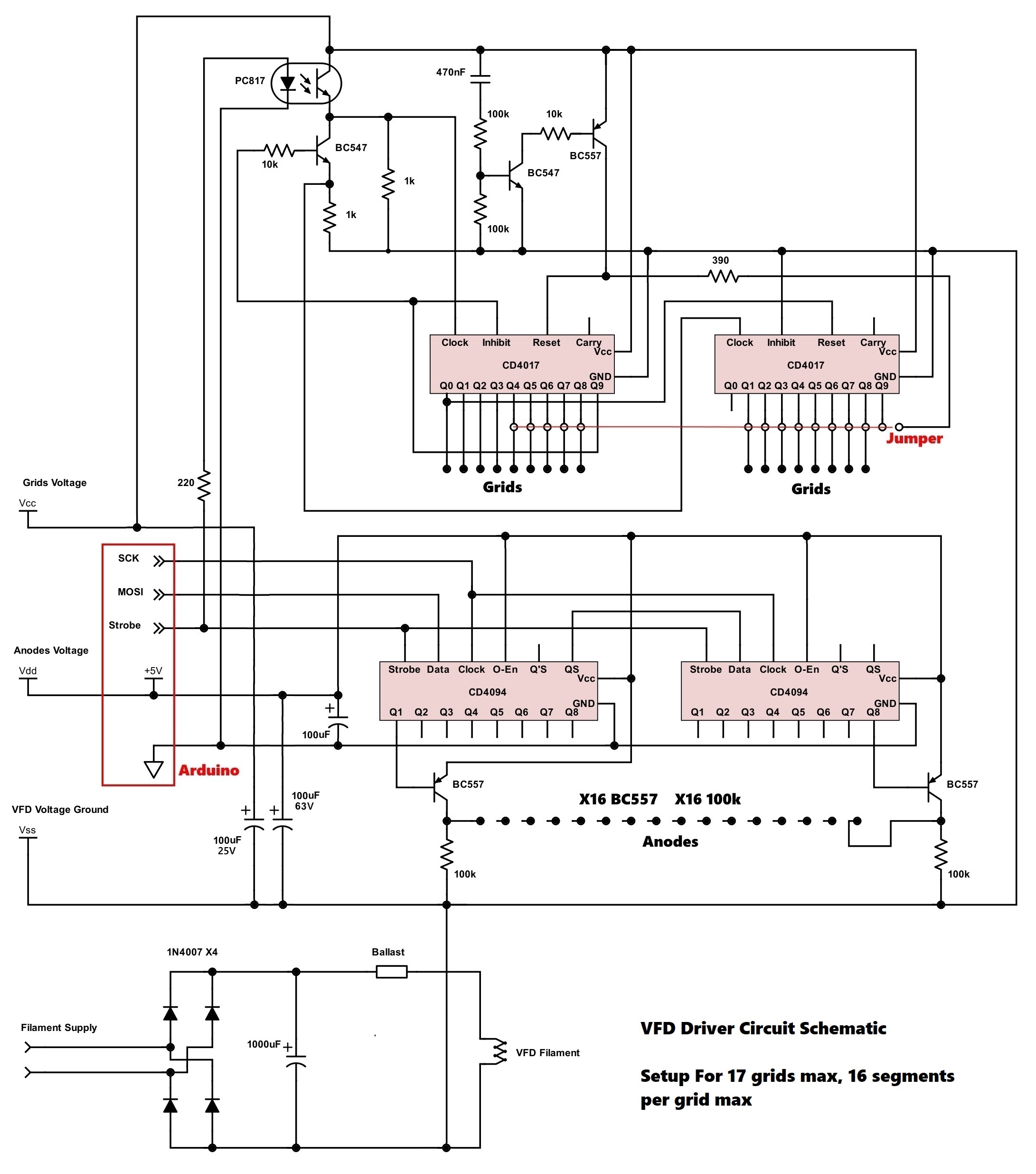
This circuit uses two types of integrated circuits of the same family, two CD4094 and two CD4017, the 4094 drive the anodes and the 4017 drive the grids instead, the 4094 can store an high\low configuration on their outputs and are good for the anodes side, the 4017 are the classic chips with 10 sequencing outputs, perfect for the grids. Once the 4094 are loaded with the moment anodes configuration, the "ok" signal (strobe) applies this setup and at the same time switches the 4017 by one step, allowing for an automatic sequencing.
The power part is basically only some BC557 transistors (or equivalent) that allow for a more wide voltage swing on the anodes, because these displays require an higher voltage than the 5V of the Arduino. The grids are driven by the 4017 directly, a PC817 optocoupler allows for a grater voltage than 5V around the 4017 and also a different voltage level from the CD4094, this simplifies A LOT the whole.
The Arduino must provide all the orchestration, it means that must store all the segments configuration and load the circuit with the anode setup at every grid switch, this means it really requires a clever code to do it beyond the user action. The code I made sets up a timer-based interrupt that re-loads the 4094 chips at every step, actually around 1000 times per second, so for 10 grids it gives a refresh rate of 100Hz, that is good. There's an array of data that stores the segments configuration and can be modified in-code, without particular procedures or subsequent actions, the interrupt routine will upload the data by it's own.
Power SuppliesThe grids voltage on the 4017 chips can be from 5Vdc to 18Vdc and at least 50mA of current, it doesn't need to be regulated. Usually (as far as I saw) 12V will suffice for every situation, increasing it doesn't appear to increase brightness much (if it's a vacuum tube, the grid doesn't require huge voltages).
The anodes voltage can be from literally 0V up to whatever your transistors can withstand (50Vdc for the BC557), usually if the display is perfect a 20-30Vdc will do the job perfectly, not regulated is good. For a normal setup 50mA of supply is more than enough.
The digital power can be 5Vdc or also 3.3Vdc in case of those types of Arduinos or MCUs (not tried yet), this requires like 100mA of power (hopefully less), in case the CD4094 become sluggish you can reduce the SPI clock in code and\or use the "Q'S" output from the first 4094 for a more consistent communication.
The filament supply must provide at least 5V 200-300mA of current, if you already have a DC source you can avoid the bridge rectifier and 1000uF capacitor, but you CANNOT use the same digital supply for\from the Arduino. The actual filament in case of a not so big appliance display runs on like 3V and can draw 150mA.
- before hooking up the wires, if you don't know what pin does what, it's better to try the display first, usually a pair of AA batteries in series will go ok for the filament (usually it's the side contacts), while a pair of 9V batts in series will provide the positive polarization for both grids and anodes; grids and anodes are often grouped, a good idea is to find the actual "anode zero" because it's quite likely the first segment on the numeric or alphanumeric part, often the same and with the same order for all the grids, putting the wires in reverse order by accident makes the software more clumsy at the end, grids instead, apparently, follow the pin order
- go easy on the filament supply, increase current little by little, stay in darkness and the moment you start seeing the filaments becoming slightly incandescent just reduce a bit and you are done, a power potentiometer is perfect, you find these sometimes in old TVs but it's difficult nowadays
- increase voltages on grids and anodes in a sane way, the phosphors can burn irreparably, the circuit also works scanning, so if the system hangs you'll provide too much power on a single grid section continuously
- play with a compromise on the grids\anodes voltages, mind that the grids could consume some current, not worth pushing on that, better mind the anodes
- using a single transformer for your entire project\setup is ideal, also some mixed solutions can be used, but switching PSUs and especially grounded ones can play you a bad prank, that's why for experimenting it's ALWAYS a good idea to use classic transformer supplies
- you can expand this driver adding some CD4094 and\or CD4017, of course if you need 8 anodes or less you can rid of the second 4094, same scenario for the 4017, but if you want the driver ready at hand just build it as much as complete possible
- there are no resistors on the bases of the anodes transistors as you can see, this gives superfast drive and narrows the parts list but makes the CD4094 consume some power, they will not heat up almost at all but some specimens of chips may have a too strong output, check current consumption in case, the chips will not blow, because the power dissipated is INSIDE the maximum allowable, current can be in the 4mA range per pin at 5V supply
- old tired displays can be renewed by some current shocks on the filaments, if it's the entire display that is dim and not just a burnt segment, they say that you bring the wires visibly incandescent (yellow) like five times in a row for a pair of seconds each time, never tried it but it may require twice the rated voltage of the filament, this cleans em but apparently it's more useful for very old\antique ones... and it's risky, those are not light bulbs, you could snap the wires
General Schematic
There's a jumper selector (running on the red line) you must configure on the 4017 chips, it resets the two 4017 at the completion of the grids scanning, you must connect (or solder) the flying jumper on the output pin AFTER the last grid, so if your display has 10 grids the jumper goes on the 11th output.
The Arduino connections are outlined in red, you can use the USB power for it but it's strongly advised to use a regular old-style transformer for the remaining supplies if you already have a grounded power supply like your PC. These supplies must be all DC except maybe the filament supply, I added some diodes because it's likely you need a separate transformer with a low voltage secondary. The filament power usually ranges around 3V 150mA, a 5V AC transformer will suffice. The "ballast" thing will possibly be a wirevound power potentiometer of like 100ohms, or a fixed resistor, or also some 1N4007 diodes to reduce the voltage.
The BC557 transistors pull the anodes up to anodic voltage and the 100kohm resistors will let the voltage drive fall when the segment is off, while the CD4094 remain at 5V normally.
The CD4017s will be powered with grid voltage and don't require additional transistors. There's a "ghetto" reset circuit for the 4017 that lasts like one tenth of a second, you have to wait for it to settle before running the code.
The "original" schematic for cascading some CD4017 required other logic gates chips, I used instead an NPN transistor and the optocoupler itself to replicate an AND gate, it's fast enough at closing so it's perfect for the task, at releasing it's instead a bit slower but we don't care, especially because the clock inputs on the 4017 are schmitt triggered and the required speed is not "scary" there.
There are various grounds for the chips and stuff as you can see, take a good look.


Comments