I don't know if someone else has come up with the same idea, but, anyway, I made it.
The project is decently simple and no requires any precision during construction (as you can see). If you are barely able to see something in the video, it's because I just don't have a nice camera; the effect is perfectly visible and neat in darkness. If you are not satisfied with light intensity, you can always use a dismissed DVD burner laser soldered on the same optics of the one I used but you will need more powerful electronics, you need a true piece of glass mirror to superglue slightly tilted on the motor pulley along with something to trigger the sensor.
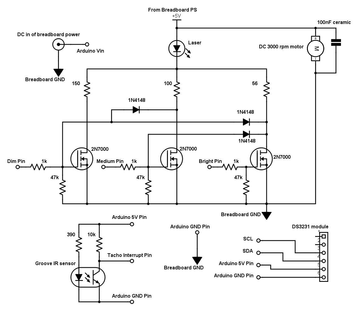
The main ideaThe principle is simple: the shutter triggers the "tacho" interrupt that resets the timers, turn period is also measured, trigger points are placed along the timer's ticking, trigger points are calculated accordingly to clock's arms positions, the mirror deflects the beam around the face of the clock and the 3 transistors are triggered at timer compares obtaining different light intensities.
I left you to add a way to adjust time, for example with two buttons, the loop()
function doesn't need to be fast.
Some tips- The sensor must be placed where the shutter just opens and the beam points at 12:00.
- The motor direction must make the beam spin clockwise (so if it doesn't, exchange wires).
- Hold the laser head with something thin as the laser wires and keep it not too close to the motor.
- DO NOT use the regulated 5V of the Arduino, RTC and sensor for the rest of the circuit, use different lines (this is always valid).
- Solder a jumper wire on the back of the center pin of the DC connector of the breadboard power supply to power the Arduino "Vin".
- If you are not satisfied with light intensities, you can always vary value of the 3 resistors that load the laser; you can even force it a bit.
- You must balance the rotating parts, place the shutter over a screwdriver shaft and see where it stays still. Also use a very small piece of mirror, place it in the middle and secure it well.
- The shutter has a shorter arm (that doesn't trigger) with a small counterweight.


Comments