Project OverviewEncoders are like Fitbits for motors. Depending on the type of encoder, they can keep track of the distance the motor traveled, the direction, or the exact angle it has turned. Typically, encoders are really small and spin at high rates. To investigate how they work, we made larger slower models of them. This project demonstrates how incremental, quadrature, and absolute encoders work.
ConstructionEncoder Disk
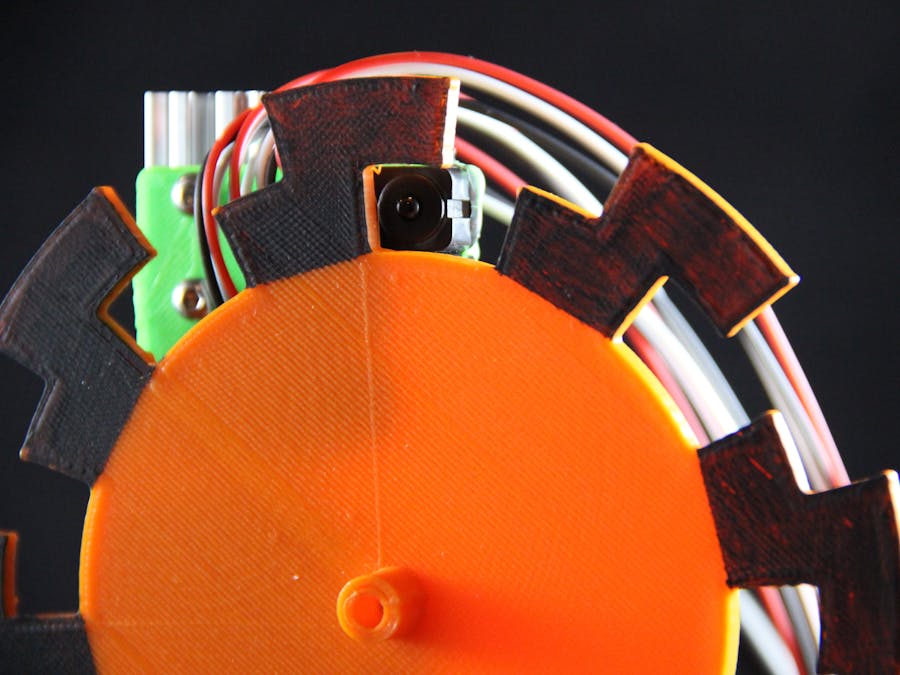
A rotary encoder is a wheel with slits that is attached to the shaft of a motor (or other device that you want to monitor the position of). Our encoders were 3D printed.
Structure
Our structure is made out of OpenBeam. We wanted something sturdy and adjustable. We wanted to be able to move the sensors up and down to align with each other and closer and father away from each other if needed. The mounts for the motor and sensors were made for OpenBeam, but you can use other materials you have.
Sensors
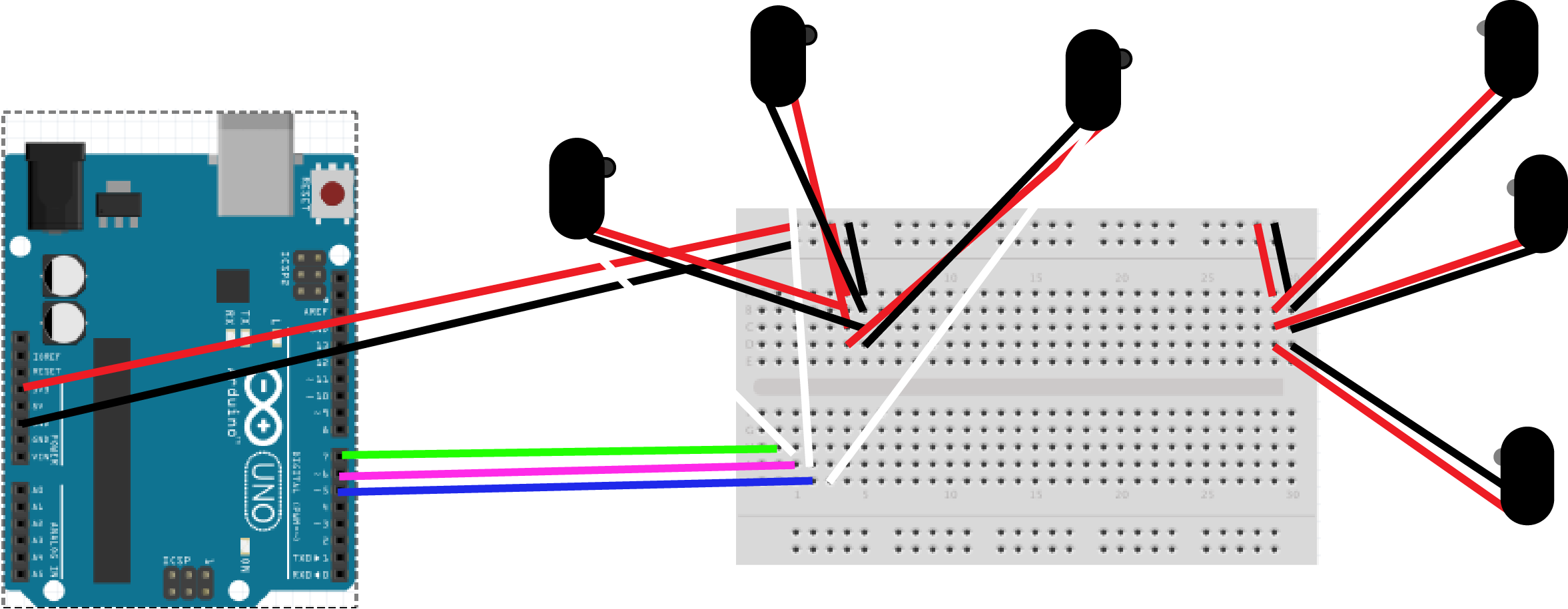
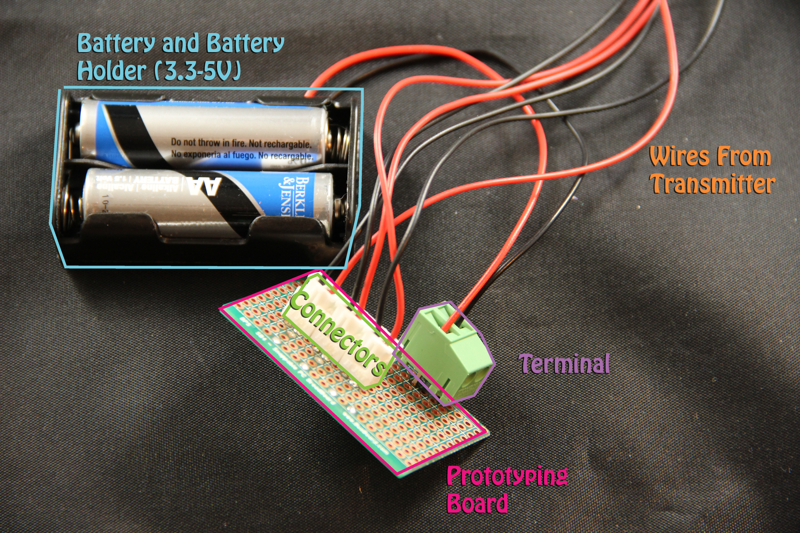
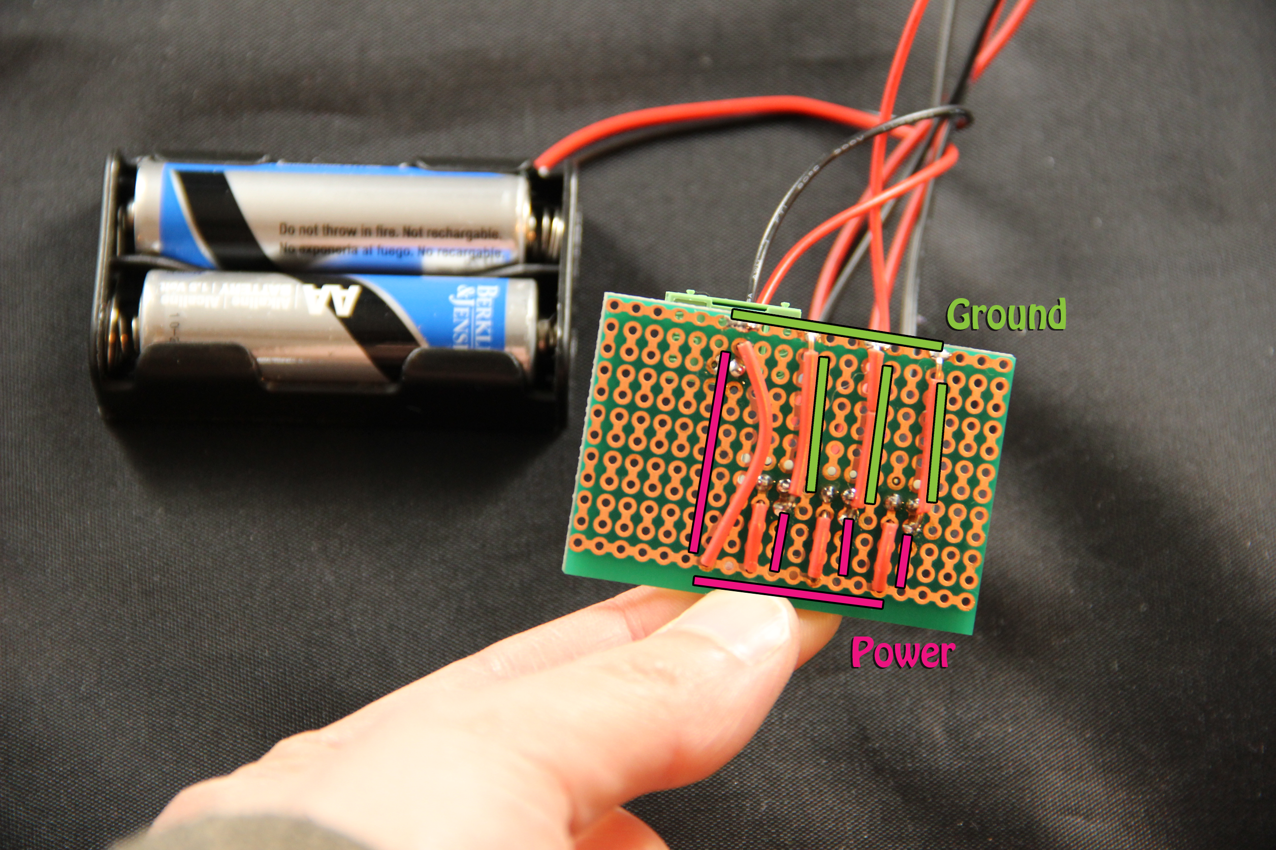
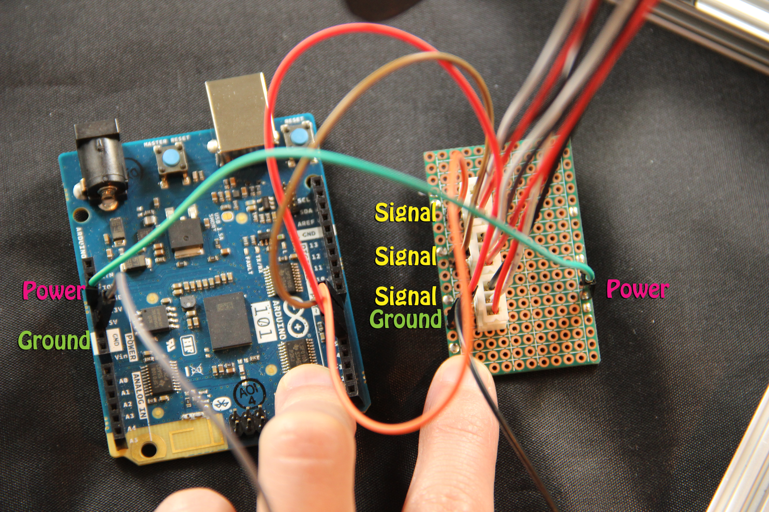
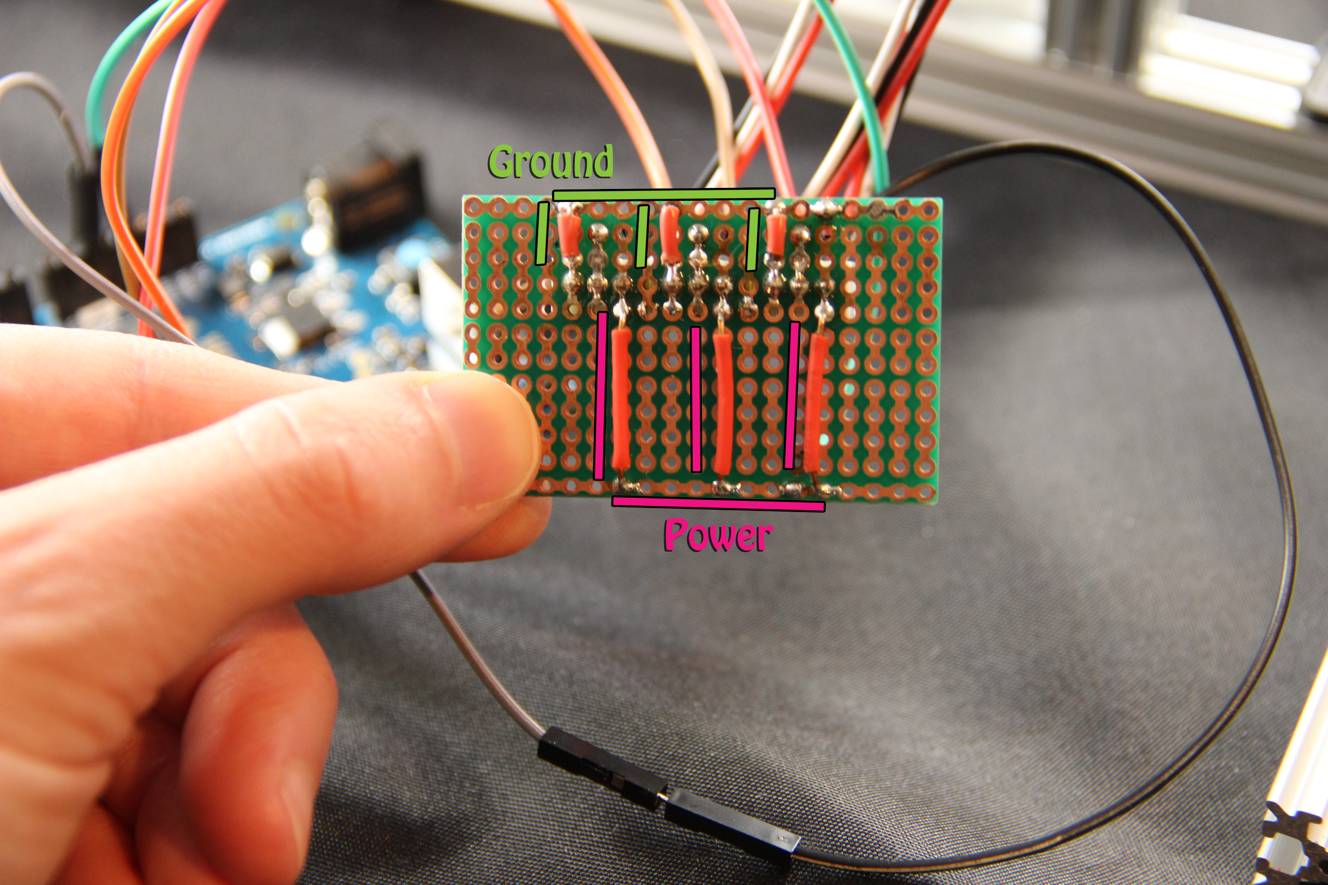
We used Adafruit's break beam sensors. You could use LDRs and LEDs. The transmitter just needs to be powered. It can be powered with 3.3-5V. We use 2 AA batteries. The black is ground and the red is power. The receiver has a white wire. This is the signal wire. which goes to digital pins 5, 6, and 7 of the Arduino. We power the receiver via the Arduino (you can power both the transmitter and receiver via the Arduino ).
Motor
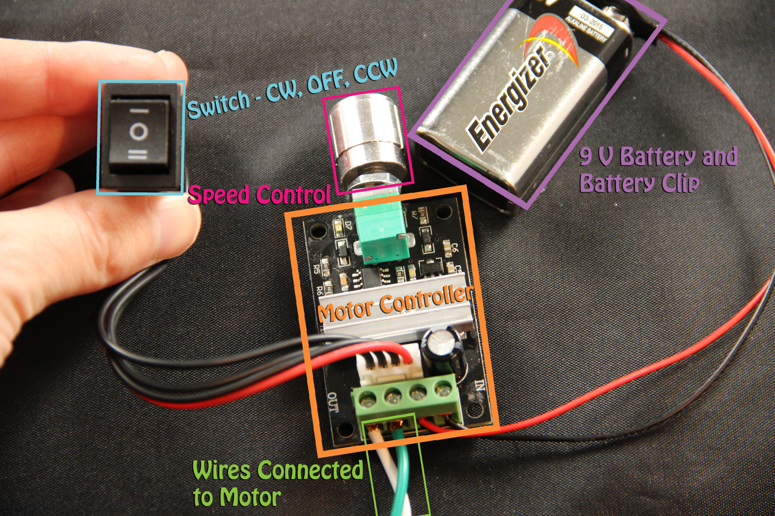
We have a larger motor and a motor controller wired to a 9V battery. You can use a smaller motor and a potentiometer to control the encoder. Just watch out for the voltage rating on the motor and change the diameter of the opening to fit your motor.
TroubleshootingThe break beam sensors use IR that can sometimes transmit through the material you are using. We had to paint our 3D printed material. The cardboard worked just fine.
We had a bad crimp causing one break beam to always ride high. Using a multimeter, we determined there wasn't a short on the board or an issue with the code.
Alternative Materials- For the detectors, you can replace the break beams with LEDs and LDRs.
- You don't have to use a 3D printer. You can just cut encoders out of cardboard.
- The motor we used was one we already had. Smaller motors will work too.
- You don't need OpenBeam. You can make the stand out of things you already have around your house/workshop/classroom.


_ztBMuBhMHo.jpg?auto=compress%2Cformat&w=48&h=48&fit=fill&bg=ffffff)


_t9PF3orMPd.png?auto=compress%2Cformat&w=40&h=40&fit=fillmax&bg=fff&dpr=2)
Comments