


Hardware components | ||||||
| × | 44 | ||||
| × | 1 | ||||
| × | 2 | ||||
| × | 1 | ||||
| × | 1 | ||||
| × | 12 | ||||
| × | 22 | ||||
| × | 1 | ||||
| × | 76 | ||||
| × | 30 | ||||
Software apps and online services | ||||||
 |
| |||||
Hand tools and fabrication machines | ||||||
 |
| |||||
 |
| |||||
| ||||||
Cycloidal Drives are the bread and butter of robotics. They are powerful gearboxes that are an industrial standard in robot arms, humanoid robots, and quadrupeds. They are especially known for their high accuracy, which is due to minimal backlash. What sets them apart from other drive variations, such as harmonic drives, is their ability to be effectively and cheaply produced by means of additive manufacturing. This allows hobbyists and enthusiasts to print such drives cheaply at home.
How it Works:Compared to traditional gearboxes, which use toothed gears, cycloidal drives use cycloidal gears. A cycloid is a mathematical shape that can be traced by a single point on the edge of a rolling circle. This cycloid shape is then repeated around a circular shape and forms "teeth". Here's the cycloidal gear within the cycloidal drive:
There are usually two cycloidal gears within a cycloidal gearbox. Both are shown above. The top one has a standard orientation with 15 cycloids. The one below has cycloids shifted 180 degrees with respect to the top one. The two cycloidal drives are eccentrically separated as well. This is done to cancel out vibrations where the cycloidal gears will make contact with the gearbox housing. This concept is visualized below. You will also notice that at every point of the cycloid gear rotation, there is always at least one cycloid in contact with the gear box housing.
Maybe the most important concept in gearbox and drive calculations is the gear reduction or gear ratio. This value explains the extent to which torque or speed will be increased compared to the original motor input. Usually, this value is calculated based on the number of gear teeth. For example, when considering the mesh of a 20-tooth gear and a 10-tooth gear, the gear ratio is simply the number of teeth of the output (10) divided by the number of teeth of the input (20): thus, the ratio is 1:2. This means that, for every single rotation of the input, the output rotates twice, resulting in an increased speed.
The case of the cycloidal gearbox is slightly different. To calculate the gear ratio of a cycloid drive: divide the number of internal lobes (15 in this case) by the solution of outer pins (16) minus the number of internal lobes (15). Thus, the ratio of 15:1 results. This means the internal shaft must rotate 15 times in order for one rotation in the outer shaft, demonstrating a massive torque increase.
Of course, this calculation only considers the ideal case. In reality, the gear ratio will be lower due to energy losses from friction and material limitations. We will discuss my "true" results in later sections.
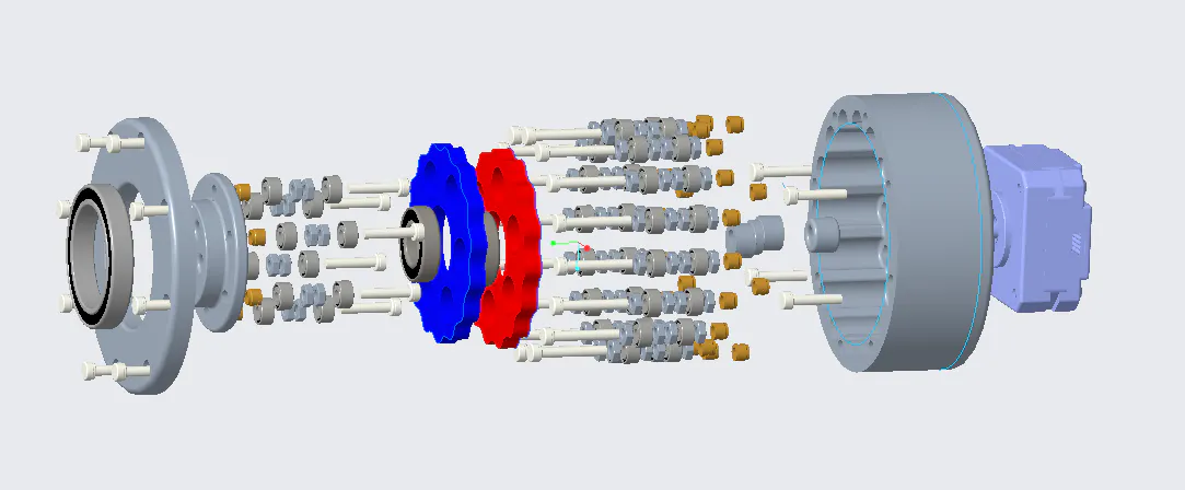
Assembly Process:Attaching the motor to the base:
Attaching the Motor Shaft to the Sleeve:
Pressfitting Cycloid Gears with 10mmx22mmx6mm Bearing:
Attaching Both Cycloidal Gears to Eccentric Shaft:
Using a Soldering Iron to Fit Inserts in Various Holes in the Base:
Assembling Outside Rollers:
Attaching Cycloid Assembly With Eccentric Shaft and Base With Outer Rollers:
Applying Grease at Every Interface of Cycloid and Bearing:
Assembling Internal Rollers:
Using a Soldering Iron to Fit Inserts in Various Holes in the Internal Spinner:
Attaching Rollers to Spinner:
Attaching Bearing to Spinner:
Attaching Cap Piece to Bearing and Spinner:
Attaching Cap to Base:
Seeing It in Action:
Testing and Final Results:Final results show that the cycloidal drive achieves 1.7 kg of force at a 100mm distance, resulting in a torque of 1.67 N · m. The equation traditionally used to determine the efficiency of a drive is as follows: Achieved/Expected, where the expected torque is the ideal case that ignores the effects of friction and other variables. For a 15:1 reduction ratio, the expected torque is 3 N·m. Thus: 1.67/3 results in an efficiency of 55%.
Conclusion:Cycloidal gears are the future of gear drives in robotics. What sets them apart is their relatively small size yet large gear reduction. They also bring low backlash, minimal noise, and are quite easy to make at home with a 3D printer and some off-the-shelf parts. The next step that needs to be taken with 3D cycloidal drives is improving the efficiency value through better material selection or lubrication methods.


Comments