

Hardware components | ||||||
 |
| × | 1 | |||
 |
| × | 1 | |||
 |
| × | 1 | |||
 |
| × | 1 | |||
 |
| × | 1 | |||
 |
| × | 1 | |||
| × | 1 | ||||
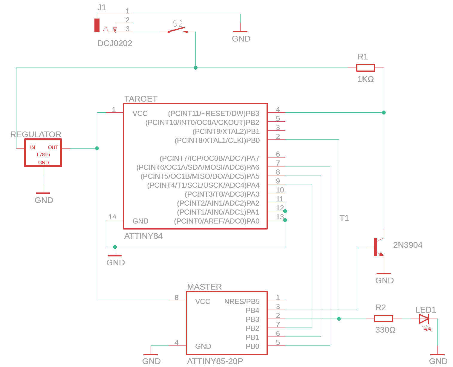
This simple and inexpensive high voltage AVR programmer for ATtiny chips requires only an ATtiny85 and a few components to build. Using Wayne Holder’s excellent ATtiny Fuse Reset posts as a starting point, this little device is able to reset the fuses on many ATtiny devices. With the correct (8-pin or 14-pin) wiring, it should be able to reset ATtiny13, 24, 25, 44, 45, 84, and 85 chips.
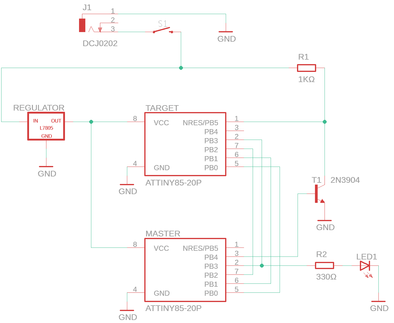
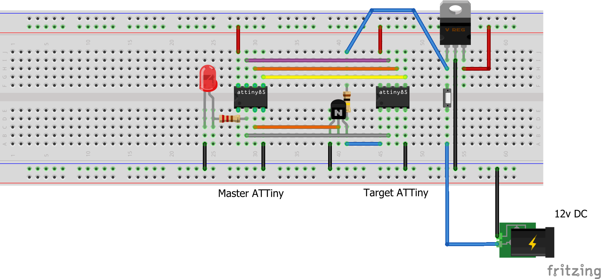
The fuse reset process requires a 12v reset signal and 5v to power the chip being reset. Wayne’s projects use a 5v power source, and either a separate 12v battery or an Arduino powered charge pump as the 12v source. To keep things simple, this project starts with a 12v power source and uses a 5v voltage regulator to provide 5v to power the ATtiny chips.
Using the ProgrammerHold the momentary switch down for a second or so. In most cases, the LED will light up very briefly (programming mode) and then turn off to indicate the reset has completed successfully.
Error Indications
If the LED stays on or begins flashing slowly, this indicates that the programmer could not read the signature of the target chip. Check the connections, and make sure both chips are plugged in completely and in the correct orientation.
If the LED flashes quickly, this indicates that the fuse reset failed – the programmer recognized the device signature and attempted to reset the fuses, but the fuse values read from the device after the reset were not as expected. In my experience, this is pretty rare.
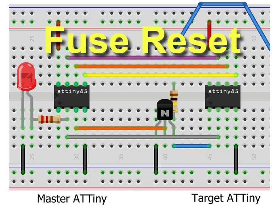
How to MakeThe circuit is so simple that it can be breadboarded in a matter of minutes. You’ll need to use an Arduino (Arduino as AVR) to load the sketch into the master ATtiny85. This must be done only once; the master chip can then be used to reset the fuses on an unlimited number of target devices.
Connections8-pin
Master	Target (8-pin)
2	2
4 GND	4 GND
5	5
6	6
7	7
8 5v	8 5v
14-pin
Master	Target (14-pin)
2	2
4 GND	11, 12, 13, 14 GND
5	7
6	8
7	9
8 5v	1 5v
In both cases, Master pin 3 goes to the base of the NPN transistor. The emitter goes to ground, and the collector goes to pin 1 of the target chip. The collector is also connected to 12v through the 1KΩ resistor.
Master pin 2 is also connected (through a 330Ω resistor) to the status LED.
Note: To keep the circuit simple, the capacitors normally surrounding the voltage regulator have been omitted. In most cases, the circuit will work fine (especially with the 7805 regulator). If you experience stability problems, a 10µF and 0.1µF capacitor connecting the input and output (respectively) to ground might be necessary.
Fuse Resetter for 8-pin chips

8-pin Schematic


Comments