


Hardware components | ||||||
 |
| × | 1 | |||
| × | 1 | ||||
 |
| × | 1 | |||
| × | 1 | ||||
 |
| × | 1 | |||
Software apps and online services | ||||||
 |
| |||||
 |
| |||||
Hand tools and fabrication machines | ||||||
 |
| |||||
 |
| |||||
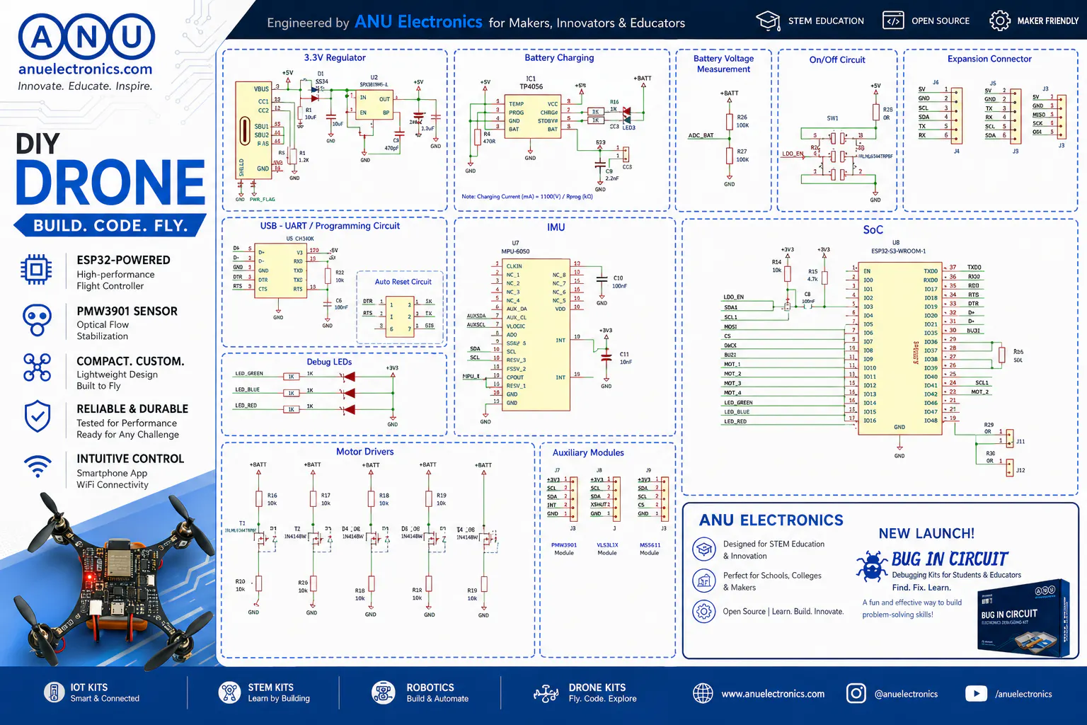
Most quadcopters follow the same pattern - a carbon fibre or plastic frame, a flight controller board mounted in the middle, ESCs on the arms, motors at the tips. It works well. It's repairable. It's the right approach for serious flying.
But I wasn't building a serious drone. I was building a learning tool.
I wanted something a student or hobbyist could pick up and immediately understand - how a flight controller works, how PID loops stabilise a quad, how IMU data feeds into motor outputs. A traditional multi-part frame hides a lot of that complexity. So I asked a simple question: what if the frame and the circuit board were the same object?
That question became the ANU PCB Drone.
The DesignThe concept is straightforward - the PCB arms are the airframe inspired from lightwing drone. An ESP32 module sits at the centre as the flight controller. Four coreless brushed motors mount directly to the board corners. No separate frame. No wiring harness. One board does everything.
The PCB is manufactured in FR4 - standard fibreglass PCB material. It's stiffer than you'd expect for the arm lengths we're using, and light enough to fly on coreless motors with a 1S LiPo battery.
Deliberate choice. Coreless brushed motors can be driven directly with PWM from the ESP32 GPIO pins - no ESC needed. That keeps the PCB simpler, the component count down, and the firmware easier to understand. For a learning platform doing indoor hover and short flights, they're perfectly adequate. Anyone wanting to scale up to BLDCs has a clear next project ahead of them.
FR4 is stiffer than most people expect. For the arm lengths on this drone, flex wasn't the problem I anticipated. The PCB material handles the static load well.
Vibration was the real issue. At higher throttle the motor harmonics transmit directly through the board to the IMU. The MPU-6050 was picking up significant noise before we soft-mounted it with foam tape. That single change made a dramatic difference to flight stability and PID loop performance.
2. Motor mount integrityThe motor mount holes are a stress concentration point. On the first prototype, we saw micro-cracking around the mount holes after several flights. Adding copper reinforcement pours around each mount point solved this — the copper distributes the stress across a larger area of the board.
3. Weight distributionCentre of gravity matters on any quadcopter. On a traditional build you can slide the flight controller and battery to adjust CoG. On an integrated PCB design, CoG is fixed by component placement at layout time. We ran several CoG calculations before committing the ESP32 module position to the final layout.
4. RepairabilityThe honest trade-off — if an arm cracks, you replace the whole board. For a learning and prototyping platform that's acceptable. For a field drone flying aggressively outdoors, it's not the right design. We're clear about this with everyone who builds one.
The FirmwareThe flight controller firmware is written in Arduino C++ and fully open source on GitHub. It covers:
- PID loop for pitch, roll, and yaw stabilisation
- MPU-6050 gyroscope and accelerometer integration
- Motor mixing algorithm for quadcopter geometry
- WiFi telemetry over UDP - streams live flight data to a browser dashboard
- Standard arming and safety logic
This was the hardest part of the whole project. Every change to the P, I, or D gains changes flight behaviour in ways that are hard to predict without flying. We ended up building a simple web interface to adjust PID gains over WiFi without reflashing - that alone saved hours of iteration time.
The WiFi telemetry dashboard streams attitude, motor outputs, and battery voltage to any browser on the same network. Open 192.168.x.x, and you can watch exactly what the flight controller is doing in real time. For learning and debugging PID behaviour, this is genuinely useful.
Specifications.Soft mounting the IMU is not optional. On a PCB airframe the vibration path from motors to IMU is very short. Without isolation the gyroscope data is too noisy for stable PID control.
Copper reinforcement around motor mounts is worth doing from day one. We learned this the hard way on prototype one.
WiFi telemetry is more useful than I expected. Being able to watch live motor outputs and attitude in a browser while someone else flies made PID tuning significantly faster.
FR4 is a surprisingly capable structural material at small scale. I expected more flex problems than we got. The limiting factor was vibration, not rigidity.
The integrated design genuinely simplifies the learning experience.A student can look at this board and understand the whole system — power, processing, sensing, and actuation — in one object. That was the goal and it works.
Take It Further- Add a camera — mount an ESP32-CAM module and stream a first-person video feed over WiFi
- Upgrade to BLDCs — add ESCs and rewrite the motor mixing for brushless control
- Tune your own PID — use the WiFi dashboard to adjust gains in real time without reflashing
- Add more sensors — barometer for altitude hold, optical flow for position hold
The ANU PCB Drone is part of CoreStack — a 5-board embedded learning kit I've been building for the past year. It covers Arduino Uno R4 WiFi, Raspberry Pi Pico 2, CYD touch display, ESP32-CAM, and STM32 Nucleo across 5 learning stages — from beginner to edge AI.
The full kit includes the drone, 145+ components, 35+ GitHub projects, and a dedicated learning platform with video courses.
CoreStack is currently on Kickstarter - follow the pre-launch page to get notified when early bird pricing opens:
Early bird starts at $99 for the Core Kit.


Comments