

Hardware components | ||||||
 |
| × | 1 | |||
 |
| × | 1 | |||
 |
| × | 1 | |||
 |
| × | 1 | |||
 |
| × | 5 | |||
 |
| × | 1 | |||
Software apps and online services | ||||||
 |
| |||||
 |
| |||||
| ||||||
Today, every business in existence has a server room. A server room is a part of a data center and is used to store, power and operate computer servers and associated equipment. These computer servers operate continuously and generate a lot of heat in the process. If a server room gets overheated, the electronic components may get permanently weakened, the servers may fail and even server room fires can be caused leading to machine damage and loss of a significant amount of data. On the other hand, the cooling systems installed in the server rooms if run at full blast, may consume a lot of energy, lead to high electricity bills and even harm the environment.
2. PROPOSED SOLUTIONIn order to prevent such scenarios, a temperature monitoring and alerting system would come in handy. The system created here monitors its surrounding temperature and if the temperature crosses certain thresholds, it sends an SMS alert to each of the registered phone numbers while simultaneously initiating an audible alert signal at the location of the server room so that the concerned personnel on-site can take care of the situation immediately.
Here, both static and dynamic thresholds are defined for the sensed temperature to ensure enhanced protection of the servers from damage. The optimal static thresholds can vary for different server rooms but the general temperature range for proper functioning of server rooms is 18°C - 27°C as stated by ASHRAE. The dynamic thresholds are calculated for anomaly detection using Z – score analysis wherein if the temperature increases or decreases suddenly, SMS and buzzer alerts are sent.
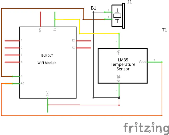
3. SETTING UP THE HARDWARELet us begin with the hardware connections. Make sure that you power ON the Bolt module only after all the connections are done. The Fritzing schematic diagram is attached and the breadboard diagram is shown below:
Follow the steps below to set up your hardware:
Step 1: Connecting The Temperature Sensor
Place the LM35 temperature sensor on the breadboard and connect its three leads via jumper wires to the respective pins of the Bolt module. Keeping the flat side of the sensor towards yourself:
a. Connect the leftmost lead which is the supply terminal to the 5V pin of the Bolt module.
b. Connect the middle lead which is the analog output terminal to the Analog Input pin (A0) of the Bolt module.
c. Connect the rightmost lead which is the ground terminal to the GND pin of the Bolt module.
Step 2: Connecting The Buzzer
Place the buzzer on the breadboard and connect its leads via jumper wires to the respective pins of the Bolt module. Remove the seal covering the buzzer opening after the connections are done.
a. Connect the longer lead which is the positive terminal (indicated by a '+' sign on the seal in the image) to GPIO pin 0 of the Bolt module.
b. Connect the shorter lead which is the negative terminal to the GND pin of the Bolt module.
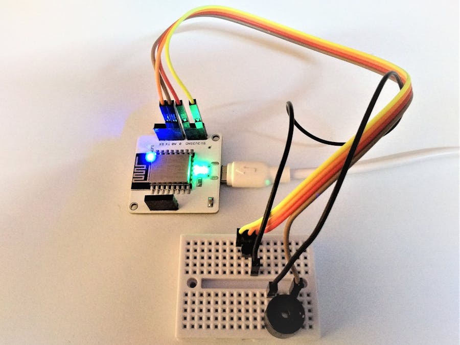
That's all for the hardware assembly. The completed system is shown below:
Now, we move on to the software configurations. The code is written using Python 3 on Ubuntu which uses Linux kernel. Follow the steps below to complete the software setup:
Step 1: Installing Ubuntu VPS (Optional)
If you don’t have Ubuntu OS on the host computer, an Ubuntu VPS can be set up by either creating a Digital Ocean Droplet or by using VMware or VirtualBox. After setting up Ubuntu, login, update the packages and install Python 3 as well as the 'boltiot' Python library.
Step 2: Creating a Twilio Account
While creating the account make sure to choose the programming language as Python and enter the phone number on which you wish to receive the SMS alerts. Post account creation, generate a Twilio phone number. Copy and save the Account SID, Auth Token and the Twilio phone number from your Twilio dashboard for entering in the configuration file which will be created later.
Step 3: Locating The API Key And Device ID
The Bolt Cloud API key can be found by clicking the 'API' tab on the dashboard of your Bolt Cloud account and the Bolt Device ID can be found by clicking on the 'Devices' tab as shown below:
The API key and the device ID can be copied directly by clicking on the copy button as shown above.
Step 4: Defining Static Thresholds
We have seen that as per ASHRAE, the general temperature range for proper functioning of server rooms is 18°C - 27°C. The temperature sensor that we are using can measure temperatures within the range -55°C to 150°C and gives an output value in analog form which is then received by the A0 pin of the Bolt module and converted to digital form by an inbuilt ADC (Analog to Digital Converter). The formula to convert this digital sensor value denoted by ‘r’ to temperature in °C denoted by ‘T’ is given by:
T = r/10.24
An equivalent of this formula is ‘r = T * 10.24’ which can be used to calculate the static thresholds in terms of digital sensor value:
Lower Threshold = 18 * 10.24 = 184.32 ≈ 184
Higher Threshold = 27 * 10.24 = 276.48 ≈ 276
If the temperature measured crosses these thresholds, a buzzer alert is sounded at the server room location and an SMS alert is sent to the phone number registered on Twilio.
Step 5: Defining Constant Parameters For Anomaly Detection
In the procedure of anomaly detection using Z – score analysis, the concept of dynamic thresholds is brought into the picture. For each new sensor value that is collected, a new Z – score is calculated based on few previously collected data points. This Z – score is then used for the calculation of the higher and lower dynamic thresholds. The current sensor value is then compared with these thresholds and if it is found to lie outside these thresholds, an anomaly is detected due to which a buzzer alert is sounded at the server room location and an SMS alert is sent to the phone number registered on Twilio.
If the temperature of the area surrounding the sensor increases or decreases suddenly, the dynamic thresholds are not able to change fast enough causing the current sensor value to lie outside the thresholds.
The formulas to be used for performing Z – score analysis are:
Where,
r – Frame size (number of previous data points)
C – Multiplication factor
Mn – Mean of the previous data points
Zn – Z – score
Vi – Current sensor value
Tn – Dynamic threshold
The constant parameters ‘r’ and ‘C’ need to be tuned as per system requirements. Here, we will be defining the frame size (r) and the multiplication factor (C) as follows:
r = 10
C = 1
Step 6: Creating a Configuration File
It’s a good practice to store all your credentials in a separate file instead of including them in your code. So, create a configuration file with ‘.py’ extension and open up nano editor to assign each of your credentials to a variable so that they can be accessed later by importing this file into your main program. Save the file after typing in the credentials.
Here, the file is named ‘conf.py’ and the contents of the file must be as follows:
SSID = 'XXXXX'                         #From Twilio dashboard
AUTH_TOKEN = 'XXXXX'                   #From Twilio dashboard
FROM_NUMBER = 'XXXXX'                  #From Twilio dashboard
TO_NUMBER = '+91XXXXX'                 #Your phone number
API_KEY = 'XXXX-XXXX-XXXX-XXXX'        #From Bolt Cloud dashboard
DEVICE_ID = 'BOLTXXXXX'                #From Bolt Cloud dashboard
FRAME_SIZE = 10
MUL_FACTOR = 1
min = 184                              #Lower static threshold
max = 276                              #Higher static threshold
Step 7: Constructing The Main Code
Create a new Python file, which will contain the main code, within the same directory as the configuration file and open the nano editor for this file. Here, the file is named ‘temp_alert.py’. Type in the code attached and save the file.
5. DEPLOYING THE SYSTEMStep 1: Powering ON The Bolt Module
Connect the micro – USB cable to the Bolt module and power ON the device making sure that the two indicator LEDs (blue and green) glow steadily to ensure that the device is connected to a WiFi network as well as to your Bolt Cloud account.
Step 2: Executing The Main Code
Once the Bolt module is connected to the Bolt Cloud, run the code in the ‘temp_alert.py’ file by typing the following command in the Terminal:
sudo python3 temp_alert.py
A. When Temperature Crosses The Static Thresholds
The attached main code considers the original thresholds but for the ease of demonstration, the static thresholds are considered to be:
min = 300
max = 350
a. Crossing Higher Bound
b. Crossing Lower Bound
B. When Temperature Crosses The Dynamic Thresholds (Anomaly Detection)
The ‘Temperature Monitoring And Two Way Alerting System’ that we have created can, thus, be used to protect server room machines from damage and prevent data loss due to overheating. A large number of such systems need to be installed in a server room in order to continuously track the temperature of all the areas of the room.


Comments