

Hardware components | ||||||
_ztBMuBhMHo.jpg?auto=compress%2Cformat&w=48&h=48&fit=fill&bg=ffffff) |
| × | 1 | |||
Today, I'll show you how to control the brightness of an LED using Arduino. This project, known as the Pulsating Lamp, is straightforward and demonstrates the use of PWM (Pulse Width Modulation) to create a smooth dimming effect.
Required Components for Arduino Pulsating LampThis book will help you to gain more knowledge about Arduino: Beginning Arduino
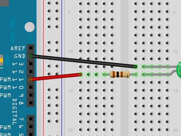
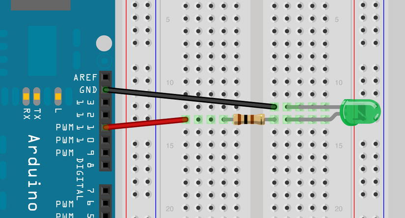
Circuit Diagram for Pulsating LampThe circuit for this project is simple. Connect a green LED, through a current-limiting resistor, between ground and Digital Pin 11 on the Arduino.
(optional caption)
Code for Pulsating Lamp
int ledPin = 11;
float sinVal;
int ledVal;

void setup() {
  pinMode(ledPin, OUTPUT);
}

void loop() {
  for (int x = 0; x < 180; x++) {
    // Convert degrees to radians then obtain sin value
    sinVal = (sin(x * (3.1412 / 180)));
    ledVal = int(sinVal * 255);
    analogWrite(ledPin, ledVal);
    delay(25);
  }
}
Upload the code to your Arduino. You will see your LED pulsate on and off steadily. Instead of a simple on/off state, the brightness will smoothly transition, creating a pulsating effect.
Explanation of the CodeThe code for this project is straightforward but requires some explanation. We first set up the variables for the LED pin, a floating-point data type for a sine wave value, and ledVal, which will hold the integer value to send out to Pin 11.
Variable Declarations:
int ledPin = 11;
float sinVal;
int ledVal;
These variables will control the LED pin, store the sine wave value, and hold the brightness value.
Setup Function:
void setup() {
  pinMode(ledPin, OUTPUT);
}
In the setup function, we initialize the LED pin as an output.
Main Loop:
void loop() {
  for (int x = 0; x < 180; x++) {
    // Convert degrees to radians then obtain sin value
    sinVal = (sin(x * (3.1412 / 180)));
    ledVal = int(sinVal * 255);
    analogWrite(ledPin, ledVal);
    delay(25);
  }
}
In the main loop, we use a for loop that goes from 0 to 179. We don't go past 180 degrees to avoid negative values, as the brightness value needs to be between 0 and 255.
Sine Wave Calculation:
sinVal = (sin(x * (3.1412 / 180)));
We use the sin() function to calculate the sine of an angle. The angle must be in radians, so we convert degrees to radians using the formula x * (3.1412 / 180).
- Sine Wave Calculation:
sinVal = (sin(x * (3.1412 / 180)));We use thesin()function to calculate the sine of an angle. The angle must be in radians, so we convert degrees to radians using the formulax * (3.1412 / 180).
Brightness Calculation:
ledVal = int(sinVal * 255);
The result of the sin() function is a number between -1 and 1. By multiplying it by 255, we get a value between 0 and 255, representing the LED's brightness. The int() function converts the floating-point value to an integer.
- Brightness Calculation:
ledVal = int(sinVal * 255);The result of thesin()function is a number between -1 and 1. By multiplying it by 255, we get a value between 0 and 255, representing the LED's brightness. Theint()function converts the floating-point value to an integer.
Analog Write:
analogWrite(ledPin, ledVal);
The analogWrite() function sends the brightness value to Digital Pin 11, controlling the LED's brightness.
- Analog Write:
analogWrite(ledPin, ledVal);TheanalogWrite()function sends the brightness value to Digital Pin 11, controlling the LED's brightness.
Delay:
delay(25);
The delay of 25 milliseconds between each step creates a smooth and steady pulsation effect.
- Delay:
delay(25);The delay of 25 milliseconds between each step creates a smooth and steady pulsation effect.
PWM (Pulse Width Modulation) is a technique to get analog results from digital means. The Arduino sends out a rectangular wave by switching the pin on and off rapidly. The pattern of on/off times simulates a varying voltage between 0 and 5V.
Duty Cycle:
The duration of the on-time is known as the pulse width. For example:
- A value of 0 sent to pin 11 will result in a 0% duty cycle (always off).
- A value of 127 will result in a 50% duty cycle (on for half the time, off for half the time).
- A value of 255 will result in a 100% duty cycle (always on).
This technique allows us to use digital pins to output a simulated analog value to the LED, creating the pulsating effect.
- Duty Cycle:
The duration of the on-time is known as the pulse width. For example:
A value of 0 sent to pin 11 will result in a 0% duty cycle (always off).
A value of 127 will result in a 50% duty cycle (on for half the time, off for half the time).
A value of 255 will result in a 100% duty cycle (always on).
This technique allows us to use digital pins to output a simulated analog value to the LED, creating the pulsating effect.
By following this guide, you can create a pulsating lamp that smoothly transitions the LED's brightness, providing a visually appealing effect. This project is a great way to understand and utilize PWM with Arduino.

Comments