

Hardware components | ||||||
| × | 1 | ||||
 |
| × | 1 | |||
 |
| × | 1 | |||
| × | 1 | ||||
 |
| × | 1 | |||
 |
| × | 1 | |||
 |
| × | 1 | |||
 |
| × | 1 | |||
Software apps and online services | ||||||
| ||||||
| ||||||
| ||||||
| ||||||
_4YUDWziWQ8.png?auto=compress%2Cformat&w=48&h=48&fit=fill&bg=ffffff) |
| |||||
| ||||||
| ||||||
Hand tools and fabrication machines | ||||||
 |
| |||||
 |
| |||||
 |
| |||||
 |
| |||||
 |
| |||||
 |
| |||||
 |
| |||||
Introduction:
This will be a series of articles in various parts that will document practical step-by-step, hands-on approach on how to program the 8051 MCU.
The target age group here are 6-16 year old rookies. The focus will be STEM platforms so most of the hardware and software that were used will be tailored for those age group but alas there is no age barrier to be honest.
PART-1: Design and Implementation of Autonomous Robot using the 8051 MCU
We will be building a small robot to show 8051 and to provide hands-on environment
Why 8051:
Historyand Trends:
The 8051 made by Intel Corporation is an 8 Bit microcontroller device used widely in many hardware ranging from washing machine, trains, vending machines, automobile, cameras, in some traffic lights, in various home appliances to mention but few of those expanding areas that incorporate 8051 microcontroller family
The 8051 chips are used in a wide variety of control systems, telecom applications, and robotics as well as in the automotive industry. By some estimations, 8051 family chips make up over 50% of the embedded chip market.
The chip was called MCS-51 by Intel, it is a single chip microcontroller (MCU) family which were developed in the 80s mainly for embedded systems applications [[i] ].The 8051 is single 8-bit MCU with many variant that enhanced it capabilities.The microcontroller have derivatives made by many vendors some of which are AT89s51, STC89c51. There are 8052 enhanced versions like the ATMEL AT89s52, NXP700, STC89c82 and many more…
According to its Wiki book [[ii]], some of the features that have made the 8051 popular are:
- 4 KB on chip program memory.
- 128 bytes on chip data memory(RAM)
- 32 bytes devoted to register banks
- 16 bytes of bit-addressable memory
- 80 bytes of general-purpose memory
- 4 register banks.
- 128 user defined software flags.
- 8-bit data bus
- 16-bit address bus
- 16 bit timers (usually 2, but may have more, or less).
- 3 internal and 2 external interrupts.
- Bit as well as byte addressable RAM area of 16 bytes.
- Four 8-bit ports, (short models have two 8-bit ports).
- 16-bit program counter and data pointer.
- 1 Microsecond instruction cycle with 12 MHz Crystal.
The chip has 40 pins divided into four 8bit ports (PO, P1, P2 and P3), about 30 of the pins are available for various programming applications. Each pin can be configure either as input or output function by reference to the port values e.g. P0^1 (means port 0 pin 1).
There are variant of 8051 microcontroller in various capacities, enhancements including large memory up to and beyond 64kb or using external large memory modules, model-specific features, such as UART, ADC, Op_Amps, etc…
There are various textbooks and Internet websites on the study of Intel 8051 microcontroller family with numerous programming resources.
Although the 8051 is famously programmed in assembly and C language but some vendor have created tools in C++, Basic, Forth and Pascal for 8051 MCU domain.
There are also development IDE like Arduino IDE for programming 8051 derivatives like the AT89s52, STC89c82 and others.
In order to be useful any microcontroller will to be programmed for the target domain. It also may need to be configured with environmental values for then intended purpose.
Basic Principles of Operation of microcontrollers
Microcontrollers are used for specific applications.
They do not need to be powerful because most applications only require a clock of a few MHz and small amount of storage.
A microcontroller needs to be programmed to be useful.
A microcontroller is only as useful as the code written for it. If you wanted to turn on a red light when a temperature reached a certain point, the programmer would have to explicitly specify how that will happen through his code.
BOM and Part Lists:
Project Building BOM:
A typical bill of materials that could be adapted is shown below:
Create Project Schematic/Circuit Diagram:
Hardware ComponentDesign in KiCad:
Here I explain the step that I went through to create circuit diagram and component layout for my maize chasing robot. I also how the hardware were wired up including their function.
The hardware and component parts were realised using the component specified in the BOM above. The following is the circuit diagram and followed by the actual hardware build in a step by step setup mode:
Schematic Diagram: This was made in KiCad [[i] ] which an open source EDA for creating circuit and PCB diagram. The source code of this brilliant software can be download at [[ii] ] for those who will like to customise for pedagogy environment.
On starting up the software you will be presented with the above layout. To the right is the EDA editor for laying out electronics components like microcontroller, capacitors, resistors, sensors, etc…
Next create a new project, give it a name e.g. MaizeRobot. Next click to select schematic symbol (see 1 in the diagram above)
You will be presented with the schematic editor where you will place your components, the wiring and routing, etc… as shown below:
Next select tools/symbol library editor
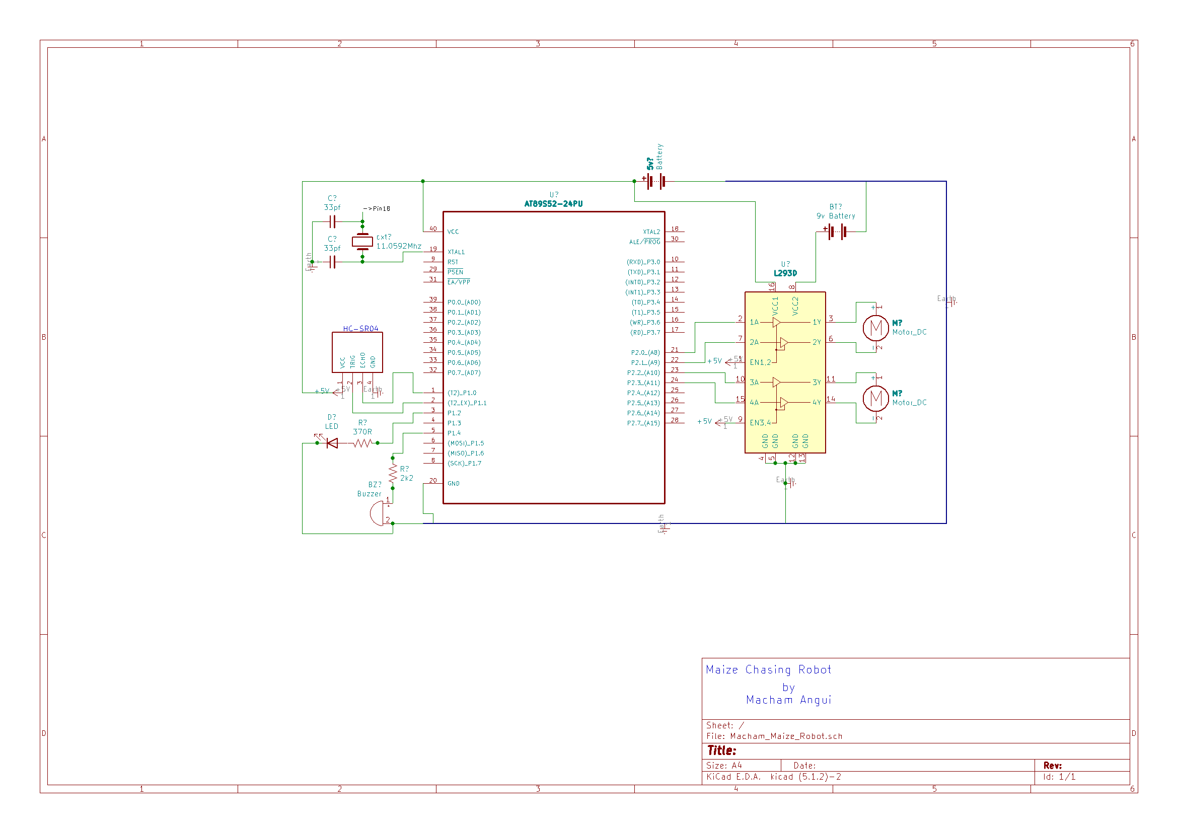
The completed schematic diagram is as shown below :
The maize chase robot electronics board was constructed based on the circuit diagram realised above.
The following steps outline how things were carried out in conjunctions with other materials including assembly and testing of the robot.
Robot Assembling:
The chassis: this was made from a PVC plastic material, initial thought was base around using a wooden material for the chassis but it quickly turn out that it will not be the right due to weight, brittleness of the wood and environment impact. Also I wanted to teach how to 3D printed the chassis and for students to be able to replicate the chassis or customised it for their creativeness. Below is the photography of the chassis as taken with my mobile phone camera:
As you can see, holes are drilled out to house gear motor, for housing other components including the electronics board, motor driver shield, ultrasonic sensor, LED, buzzer, etc...
Component Assembly: individual component is assembled and tested before being mounted into the chassis and couple by wires with other electronics components.
Ultrasonic Sensor: as you can see from the schematics diagram, the ultrasonic range sensor whose main function is to detect objects along the robot path and to measure their distance from the robot.
From the datasheet [ [i]], the following information were extracted:
Ultrasonic Sensor Pin Configuration:
- · Operating voltage: +5V
- · Theoretical Measuring Distance: 2cm to 450cm
- · Practical Measuring Distance: 2cm to 80cm
- · Accuracy: 3mm
- · Measuring angle covered: < 15°
- · Operating Current: < 15mA
- · Operating Frequency: 40Hz
AboutHC-SR04:
The HC-SR04 ultrasonic sensor uses sonar wave to determine distance to an object just like bats or dolphins do. It offers excellent non-contact range detection with high accuracy and stable readings in an easy-to-use package. From 2cm to 400 cm or 1” to 13feet. It operation is not affected by sunlight or black material like Sharp rangefinders are (although acoustically soft materials like cloth can be difficult to detect). It comes complete with ultrasonic transmitter (labelled:T ) and receiver module (labelled: R ).
OPERATION:
The timing diagram of HC-SR04 is shown below here. When initialised and working, for measuring the distance of an obstacle object, the Trig (Trigger) of SR04 must receive a pulse of high (5V) for at least 10us, this will initiate the sensor and it will transmit out 8 cycle of ultrasonic burst at 40 kHz. It will then wait for the reflected ultrasonic burst. When the sensor detected the reflected ultrasonic from its receiver, it will set the Echo pin to high (5V) and delay for a period(width) which proportion to distance. To obtain the distance, measure the width(Ton) of Echo pin. According to datasheet, the cycle period for HC-SR04 must not be below 50mS.
The distance can be calculated from the echo pulse width using the following equations.
- Distance in cm = echo pulse width in uS/58 (for values in cm)
- Distance in inch = echo pulse width in uS/148 (for values in inch)
The Formula:
Time = Width of Echo pulse, in uS (micro second)
Distance in centimetres = Time / 58Distance in inches =Time / 148Or you can utilise the speed of sound, which is 340m/s
In this project use the HC-SR04 was mounted on a breadboard to permit various testing and use cases/scenarios but in real-life it needs to be soldered and position well from reflecting objects.
Here is the screenshot of my implementation of the HC-SR04 for my robot:
The DC Dual Axis Plastic GearboxMotor:
Motor used in this project is a dual axis DC gear motor with the following operating values:
The motor is DC Dual Axis Plastic Gearbox Motor with a gear ratio of 1:48[[i] ]. Two of this were used in this project labelled M1 and M2 in my schematic diagram.
We control its speed using the AT89S52 microcontroller generated pulse width modulation wave.
The motors can be powered between 3VDC up to 9VDC. At 6VDC about 160mA at speed 250 RPM no-load, and 1.5 Amps when loaded.
DC Motor Features:
Rated Voltage: 3~9VContinuous No-LoadCurrent: 150mA +/- 10%Min. OperatingSpeed (3V): 90+/- 10% RPMMin. OperatingSpeed (6V): 200+/- 10% RPMTorque: 0.15Nm~0.60NmStall Torque (6V):0.8kg.cmGear Ratio: 1:48Body Dimensions: 70x 22 x 18mmWeight: 30.6g
The L293D: Motor Driver:
L293D motor driver is employed in this project. The driver circuit was constructed as given from the schematic diagram shown earlier.
The AT89S52 microcontroller can only output about 70 milliamp. As you can from my discussion on the DC motor above, this will not be enough to drive the dual axis DC gear motor used in this project hence we need a motor driver that drive larger loads.
This is an integrated circuit (IC) module that operates as a “Quadruple Half-H Drivers”. The IC can be configured to drive two DC motors or a stepper motor (2 phase). According to the datasheet [ [i]], it has the following operating modes and features:
Features:
WideSupply-Voltage Range: 4.5 V to 36 VSeparateInput-Logic SupplyInternalESD ProtectionThermalShutdownHigh-Noise-ImmunityInputsFunctionalReplacements for SGS L293 and SGS L293DOutputCurrent 1 A per Channel (600 mA for L293D)PeakOutput Current 2 A per Channel (1.2 A for L293D)OutputClamp Diodes for Inductive Transient Suppression (L293D)
L293D Product Brief:
- It can provide bidirectional drive currents of up to 1 A at voltages from 4.5 V to 36 V.
- Typical bidirectional drive currents of up to 600-mA at voltages from 4.5 V to 36 V.
- It can drive inductive loads such as relays, solenoids, dc and bipolar stepping motors, as well as other high-current/high-voltage loads in positive-supply applications.
- All inputs are TTL compatible. Each output is a complete totem-pole drive circuit, with a Darlington transistor sink and a pseudo-Darlington source.
- Drivers are enabled in pairs, with drivers 1 and 2 enabled by 1, 2 EN and drivers 3 and 4 enabled by 3, 4 EN. When an enable input is high, the associated drivers are enabled and their outputs are active and in phase with their inputs.
- When the enable input is low, those drivers are disabled and their outputs are off and will be in high-impedance state.
With the proper data inputs, each pair of drivers forms a full-H (or bridge) reversible drive suitable for solenoid or motor applications. We use the motor application configuration in this maize chasing robot project.
Opposite is the screenshot of the section from the schematic showing L293D used in the project
and how it is connected with the two Dual Axis gear motors in my projects. Because I always wanted to learn more on how to build a motor driver from scratch, I opted to assembly the L293D on breadboard as oppose to buying a ready made motor shield.
Below here are the steps taken to realise the actual motor driver implementation in my project:
NOTE: The L293D were connected to the AT89s52 through P2.0 and P2.1 pins for Motor 1 and through P2.2 and P2.3 pins for Motor 2. Please sees the cut section of its schematic diagram as shown above.
Assembling the AT89s52 Microcontroller:
I have already covered the literature part of the 8051 as known as Intel C51 in the introduction paragraph and in the evolution trends of 8051 family of microcontroller which give rise to the AT89S52 as well.
Here the focus will be on the realisation and the usage of the AT89s52 in my project. Since this is the brain of my whole robot then it’s deserved a good coverage here.
Design and building circuit was never a straight forward experiments. There are many reason behind these, compiler problems, in-circuit programmer issues and various issues from power supply to decoupling, etc…
First here is the whole schematic circuit for the robot showing how everything is wired up together. Pin functions and connections were based its datasheet from Microchip website [[i] ]
Components and their connections:
- Crystal Oscillator: Connected between pin 18 and pin 19 as shown in the circuit diagram. Two 33 Pico farad ceramic capacitors were across the crystal oscillator and having their other end pins grounded as shown in the above schematic diagram. The chose oscillating frequency was 11.0592 MHz
I actually order some 12 MHz types but it since it many weeks if not month before arriving from China and it is difficult to find in UK and the Maplin store no longer in operation.
- Ultrasonic Range Sensor: Connected to port P1.0 and P1.1 of AT89S52 more about this later, the code that was written for making the HC-SR04 to work. Its operation and features already discussed above
- The LED and Buzzer Alarm: We introduced an LED (light emitting diode) which was connected to port P1.2 with a 370 -ohm resistor and programmed to light up (ON) whenever an obstacle within given range is detected by the robot. This is about 25cm coded in the C-language. This will be explained more in the code exploration sector of this project.
- The buzzer performs the same function just like the LED but outputs sound signal instead of light signal. The buzzer was connected to port P1.3 with a limiting 2k2 ohm resistor.
- Power supplies: the project was driven by two power supply rails both were power by two separate batteries in order to reduce load and quick drain on the battery for a longer operating periods. Two 9v gallon shape batteries.
A 9v volt battery was connected through a step down converter to obtained the necessary 5v needed to power the AT89s52 and Ultrasonic HC-SR04 sensor units while the other 9v was connected to the pin 8 (VCC-2) of the L293D motor driver device.
The complete assembly: the screenshot of the whole robot ready for testing and fine tuning is as shown below:
End of Part-1 of this series:
In the next part of this series, we will be looking at the programming side of our 8051 MCU robotics project where I will explain the algorithms that powers the robot and its accompanying C-language code that implements those algorithms. We will also show alternative programming platform for Python, Block based on Blockly and many more.... See You in Part-2
Till Then Cheerio and happy hardware hacking!
Bibliography:
[i]https://en.wikipedia.org/wiki/Intel_MCS-51
[ii]https://en.wikibooks.org/wiki/Embedded_Systems/8051_Microcontroller
[i]https://docs.google.com/document/d/1Y-yZnNhMYy7rwhAgyL_pfa39RsB-x2qR4vP8saG73rE/edit
[i]https://www.cytron.io/p-3v-6v-dual-axis-tt-gear-motor?src=us.paviewed.c
[i]http://www.ti.com/lit/ds/symlink/l293.pdf
[i]http://ww1.microchip.com/downloads/en/devicedoc/doc1919.pdf

_Ujn5WoVOOu.png?auto=compress%2Cformat&w=40&h=40&fit=fillmax&bg=fff&dpr=2)


Comments