
In this project, we will show you how to build a simpler version of an indoor garden system, which can do the hard work for you and take good care of your plants. If you are interested in developing a fully-functional indoor garden, find our previous project Fully-Functional Smart Indoor Garden.
What to expect- Remotely controlled and monitored with an app
- Monitor soil moisture
- Automatic grow light filling
- Self-watering
- Custom grow light colors
We use Tuya Sandwich Wi-Fi SoC master control board (WB3S) as the master control and design a functional board to implement the following functions:
- Provide 12V DC power supply.
- Control the water pump.
- Read analog values from the soil moisture sensor.
- Control the grow light board.
Design description:
- Circuit diagram (Download)
- PCB design (Download)
- PCB layout (Download Gerber file)
- PCB Coordinate (Download)
- BOM (Download)
Step 2: Design grow light board
1. Grow light spectruAccording to the spectrum characteristics, we choose the following five grow light sources to make the light board.
- 2835 warm white LED (Download specification)
- 2835 red (660 nm) LED (Download specification)
- 2835 blue LED (Download specification)
- 2835 green LED (Download specification)
- 2835 infrared (850 nm) LED (Download specification)
Note: The green light acts as ambient light and rarely affects plant growth. You can choose the beads to suit your preference. Your beads should match the circuit, particularly the red light and infrared parts. The light board schematics and MT7201C related specifications will be helpful.MT7201C_E.pdf
- Circuit diagram (Download)
- PCB design (Download)
- PCB layout (Download Gerber file)
- Grow light board PCB coordinate (Download)
- BOM (Download)
Cut 8 mm acrylic sheet, heat it to a degree of softness, and bend it to the desired shape.
The water tank is divided into two compartments, one for storing water and the other for placing PCBs. We use polylactide (PLA) to 3D print this water tank.
- Water reservoir lid (Download STL file)
- Water tank body lid (Download STL file)
- Water tank body (Download STL file)
You can find them in the Materials part.
Step 5: Prototype on Tuya IoT Platform
To proceed with TuyaOS development, you need to create an indoor garden product on the Tuya IoT Platform and then get the SDK. This product represents all the IoT functions of a smart garden, including product authorization and configuration, which builds the communication between the garden and the Tuya IoT Platform. This section describes how to create a smart indoor garden on the Tuya IoT Platform. For more information, see Create Products.
1.Log in to the Tuya IoT Platform, and click Create.
2.Select Small Home Appliances > Plant Grower.
3. Click Custom Solution > Plant Grower. Enter a product name, select WiFi+Bluetooth for protocol type, and click Create Product at the bottom of this page.
4.In Create Standard Functions, select Switch, Pump, Countdown, Left Time, and Fault. The function name and specific enum values can be customized.
5.Find Custom Functions and click Create Functions. Set properties for a custom function. For the specific property value, see the following figure. To implement the non-standard functions of a smart garden, you need to customize some functions.
- Add four custom functions, Red light, Green light, Blue light, and Warm white light, to adjust the brightness of the grow light.
- Add Light switch of Boolean type to turn on or off the light.
- Add Soil moisture of enum type to set a threshold for triggering auto watering.
6.When you complete function definition, click Device Panel to select a favorite app control panel. It is recommended to select the Debug Panel to suit your debugging needs.
You have finished creating a product on the Tuya IoT Platform. It is ready to proceed with embedded system development.
Step 6: CodingThe embedded code is based on the BK7231 chipset and developed with Tuya’s general Wi-Fi SDK. You can download the demo routine and find the sample code.
1. Entry to applicationThe apps folder contains application code. The structure of the application code is as follows:
├── src
|    ├── plant_driver
|    |      └── plant_pwm.c      // PWM driver. The PWM API on the SoC layer is called and re-encapsulated.
|    ├── plant_soc               // APIs running on the SoC layer
|    ├── tuya_device.c           // Entry file of application layer
|    ├── app_plant.c             // The application layer
|    └── plant_control.c         // Control logic of each functional component
|
├── include				// Header file directory
|    ├── plant_driver
|    |      └── plant_pwm.h
|    ├── plant_soc
|    ├── tuya_device.h
|    ├── app_plant.h
|    └── plant_control.h
|
└── output              // Production
Open tuya_device.c and find the device_init function.
OPERATE_RET device_init(VOID)
{
OPERATE_RET op_ret = OPRT_OK;
UCHAR_T connect_mode = 0;
PR_NOTICE("goto device_init!!!");
TY_IOT_CBS_S wf_cbs = {
status_changed_cb,\
gw_ug_inform_cb,\
gw_reset_cb,\
dev_obj_dp_cb,\
dev_raw_dp_cb,\
dev_dp_query_cb,\
NULL,
};
connect_mode = GWCM_OLD;
op_ret = tuya_iot_wf_soc_dev_init_param(connect_mode,WF_START_SMART_FIRST,&wf_cbs,NULL,PRODECT_KEY,DEV_SW_VERSION);
if(OPRT_OK != op_ret) {
PR_ERR("tuya_iot_wf_soc_dev_init_param error,err_num:%d",op_ret);
return op_ret;
}
op_ret = tuya_iot_reg_get_wf_nw_stat_cb(wf_nw_status_cb);
if(OPRT_OK != op_ret) {
PR_ERR("tuya_iot_reg_get_wf_nw_stat_cb is error,err_num:%d",op_ret);
return op_ret;
}
op_ret = app_plant_init(APP_PLANT_NORMAL);
if(OPRT_OK != op_ret) {
PR_ERR("plant init err!");
return op_ret;
}
return op_ret;
}
In the development environment for the BK7231T chipset, the device_init function is the entry to the application code. When the device is powered on, the adaptation layer runs the initialization code and then calls this function to initialize the application layer. This function deals with the followings:
1.Call tuya_iot_wf_soc_dev_init_param() for SDK initialization to configure working mode and pairing mode, register callback functions, and save the firmware key and PID. The macro definition for PID is PRODECT_KEY in code.
TY_IOT_CBS_S wf_cbs = {
status_changed_cb,\
gw_ug_inform_cb,\
gw_reset_cb,\
dev_obj_dp_cb,\
dev_raw_dp_cb,\
dev_dp_query_cb,\
NULL,
};
connect_mode = GWCM_OLD;
op_ret = tuya_iot_wf_soc_dev_init_param(connect_mode,WF_START_SMART_FIRST,\
&wf_cbs,NULL,PRODECT_KEY,DEV_SW_VERSION);
if(OPRT_OK != op_ret) {
PR_ERR("tuya_iot_wf_soc_dev_init_param error,err_num:%d",op_ret);
return op_ret;
} op_ret = tuya_iot_reg_get_wf_nw_stat_cb(wf_nw_status_cb);
    if(OPRT_OK != op_ret) {
        PR_ERR("tuya_iot_reg_get_wf_nw_stat_cb is error,err_num:%d",op_ret);
        return op_ret;
    }
op_ret = app_plant_init(APP_PLANT_NORMAL);
if(OPRT_OK != op_ret) {
PR_ERR("plant init err!");
return op_ret;
}
2.Call tuya_iot_reg_get_wf_nw_stat_cb() to register callback of device network status.
op_ret = tuya_iot_reg_get_wf_nw_stat_cb(wf_nw_status_cb);
    if(OPRT_OK != op_ret) {
        PR_ERR("tuya_iot_reg_get_wf_nw_stat_cb is error,err_num:%d",op_ret);
        return op_ret;
    }
3.Call the initialization function in the application layer.
op_ret = app_plant_init(APP_PLANT_NORMAL);
    if(OPRT_OK != op_ret) {
        PR_ERR("plant init err!");
        return op_ret;
}The application code is implemented in three layers.
- The bottom layer contains the driver code of PWM and sensors and encapsulates APIs for sensor initialization and data collection. In this project, we only use a soil moisture sensor whose analog output is processed using ADC, so only the PWM API on this layer will be called.
- The second layer has part of control logic code and calls sensor driver API to implement the control logic of each component. This layer packages API of polling data processing.
- The first layer creates application tasks to call the API in the second layer, processes DP data transmission, and accepts parsing.
app_plant.c implements the first layer.
app_plant_init()calls device initialization API packaged in the second layer and creates application tasks.
OPERATE_RET app_plant_init(IN APP_PLANT_MODE mode)
{
    OPERATE_RET op_ret = OPRT_OK;


    if(APP_PLANT_NORMAL == mode) {

        // Initialize I/O, sensors, PWM, and more
        plant_device_init();

        // Create data collection tasks for ADC sensors
        tuya_hal_thread_create(NULL, "thread_data_get_adc", 512*4, TRD_PRIO_4, sensor_data_get_adc_theard, NULL);

        // Create data processing tasks
        tuya_hal_thread_create(NULL, "thread_data_deal", 512*4, TRD_PRIO_4, sensor_data_deal_theard, NULL);

        // Create scheduled tasks for DP data reporting
        tuya_hal_thread_create(NULL, "thread_data_report", 512*4, TRD_PRIO_4, sensor_data_report_theard, NULL);

    }else {
        // Non-production test mode
    }

    return op_ret;
}app_report_all_dp_status()reports all DP data.
VOID app_report_all_dp_status(VOID)
{
    OPERATE_RET op_ret = OPRT_OK;

    INT_T dp_cnt = 0;
    dp_cnt = 12;

    TY_OBJ_DP_S *dp_arr = (TY_OBJ_DP_S *)Malloc(dp_cnt*SIZEOF(TY_OBJ_DP_S));
    if(NULL == dp_arr) {
        PR_ERR("malloc failed");
        return;
    }

    memset(dp_arr, 0, dp_cnt*SIZEOF(TY_OBJ_DP_S));

    dp_arr[0].dpid = DPID_SWITCH_P;
    dp_arr[0].type = PROP_BOOL;
    dp_arr[0].time_stamp = 0;
    dp_arr[0].value.dp_value = plant_ctrl_data.Switch;
    ......

    op_ret = dev_report_dp_json_async(NULL,dp_arr,dp_cnt);
    Free(dp_arr);
    if(OPRT_OK != op_ret) {
        PR_ERR("dev_report_dp_json_async relay_config data error,err_num",op_ret);
    }

    PR_DEBUG("dp_query report_all_dp_data");
    return;
}- In a task,
plant_get_adc_sensor_data(),plant_ctrl_handle(), andplant_ctrl_all_off()are APIs on the second layer, which are implemented inplant_control.cfile.
STATIC VOID sensor_data_get_adc_theard(PVOID_T pArg)
{
    while(1) {

        PR_DEBUG("plant_get_adc_sensor_data");
        tuya_hal_system_sleep(TASKDELAY_SEC*2);

        if(TRUE == plant_ctrl_data.Switch) {
            plant_get_adc_sensor_data();
        }

    }
}

STATIC VOID sensor_data_deal_theard(PVOID_T pArg)
{
    while(1) {
        tuya_hal_system_sleep(TASKDELAY_SEC);

        if(TRUE == plant_ctrl_data.Switch) {
            plant_ctrl_handle();
        }else {
            plant_ctrl_all_off();
        }

    }

}

STATIC VOID sensor_data_report_theard(PVOID_T pArg)
{
    while(1) {
        tuya_hal_system_sleep(TASKDELAY_SEC*5);
        app_report_all_dp_status();
    }

}deal_dp_proc()processes the received DP data according to the DP ID.
VOID deal_dp_proc(IN CONST TY_OBJ_DP_S *root)
{
    UCHAR_T dpid;

    dpid = root->dpid;
    PR_DEBUG("dpid:%d",dpid);

    switch (dpid) {

    case DPID_SWITCH_P:
        PR_DEBUG("set switch:%d",root->value.dp_bool);
        plant_ctrl_data.Switch = root->value.dp_bool;
        break;

    case DPID_PUMP:
        PR_DEBUG("set pump:%d",root->value.dp_bool);
        plant_ctrl_data.Pump = root->value.dp_bool;
        break;

        ......

    default:
        break;
    }

    return;

}
We have built the application architecture. And next, we need to implement API in the second layer, which is placed in plant_control.c. Next, we will see how to implement each function.
Dim the warm white and multi-color light with an app to provide the spectrum needed for plant growth.
The PWM output controls light brightness. The PWM initialization and output functions are implemented in plant_pwm.c. Initialize PWM in plant_device_init() and call the API to implement light control in plant_ctrl_handle().
USER_PWM_DUTY_T user_pwm_duty = {0};
VOID plant_device_init(VOID)
{
......
plant_pwm_init();
......
}
STATIC VOID __set_pwm_duty(VOID)
{
user_pwm_duty.duty_red = (USHORT_T)(((float)plant_ctrl_data.Red_value/255.0)*1000);
user_pwm_duty.duty_green = (USHORT_T)(((float)plant_ctrl_data.Green_value/255.0)*1000);
user_pwm_duty.duty_blue = (USHORT_T)(((float)plant_ctrl_data.Blue_value/255.0)*1000);
user_pwm_duty.duty_warm = (USHORT_T)(((float)plant_ctrl_data.Warm_value/255.0)*1000);
}
STATIC VOID __initiative_ctrl_module_light(VOID)
{
if (plant_ctrl_data.Countdown_set != cancel)
{
if(IsThisSysTimerRun(light_timer) == FALSE) {
light_flag_min = (USHORT_T)plant_ctrl_data.Countdown_set * 60;
plant_pwm_set(&user_pwm_duty);
sys_start_timer(light_timer,1000*60,TIMER_CYCLE);
}else {
plant_pwm_set(&user_pwm_duty);
}
}else {
light_flag_min = 0;
if(TRUE == plant_ctrl_data.Light_switch) {
plant_pwm_set(&user_pwm_duty);
}else {
plant_pwm_off();
}
}
plant_report_data.Countdown_left = light_flag_min;
}
VOID plant_ctrl_handle(VOID)
{
......
__set_pwm_duty();
__initiative_ctrl_module_light();
}The soil moisture sensor outputs different analog signal values according to the change of soil resistance. The ADC converts analog signals from the sensor into digital signals to monitor the change of moisture.
In app_plant.c, the ADC collection task calls plant_get_adc_sensor_data() in plant_control.c in a loop. All ADC collection related code is placed in this API:
VOID plant_get_adc_sensor_data(VOID)
{
tuya_hal_adc_init(&tuya_adc);
tuya_hal_adc_value_get(TEMP_ADC_DATA_LEN, &soil_moisture_value);
PR_NOTICE("water_tank_value = %d",soil_moisture_value);
tuya_hal_adc_finalize(&tuya_adc);
}
The functional board compares the obtained soil moisture value with the threshold and determines whether to water plants. You can set the threshold on the app. Manual watering is also possible. Just enable Pump on the app to supply water to your plants.
Call the watering control API in plant_ctrl_handle(). The ADD_WATER_COUNT and ADD_WATER_READY variables enable a rest-interval for the water pump to avoid overwatering plants.
STATIC VOID __passive_ctrl_module_soil_humidity(VOID)
{
if(!ADD_WATER_READY) {
tuya_gpio_write(WATER_PUMP_PORT, WATER_PUMP_LEVEL);
ADD_WATER_COUNT++;
if(ADD_WATER_COUNT >15) {
ADD_WATER_READY = 1;
ADD_WATER_COUNT = 0;
}
}
switch (plant_ctrl_data.soil_moisture_level) {
case manual_control:
ADD_WATER_COUNT == 0;
ADD_WATER_READY == 1;
break;
case low:
if(soil_moisture_value > soil_moisture_threshold.Low) {
if(ADD_WATER_READY) {
tuya_gpio_write(WATER_PUMP_PORT, !WATER_PUMP_LEVEL);
ADD_WATER_COUNT++;
if(ADD_WATER_COUNT > 2) {
ADD_WATER_READY = 0;
}
}
}else {
tuya_gpio_write(WATER_PUMP_PORT, WATER_PUMP_LEVEL);
}
break;
case medium:
if(soil_moisture_value > soil_moisture_threshold.Medium) {
if(ADD_WATER_READY) {
tuya_gpio_write(WATER_PUMP_PORT, !WATER_PUMP_LEVEL);
ADD_WATER_COUNT++;
if(ADD_WATER_COUNT > 2) {
ADD_WATER_READY = 0;
}
}
}else {
tuya_gpio_write(WATER_PUMP_PORT, WATER_PUMP_LEVEL);
}
break;
case high:
if(soil_moisture_value > soil_moisture_threshold.High) {
if(ADD_WATER_READY) {
tuya_gpio_write(WATER_PUMP_PORT, !WATER_PUMP_LEVEL);
ADD_WATER_COUNT++;
if(ADD_WATER_COUNT > 2) {
ADD_WATER_READY = 0;
}
}
}else {
tuya_gpio_write(WATER_PUMP_PORT, WATER_PUMP_LEVEL);
}
break;
default:
break;
}
}
STATIC VOID __initiative_ctrl_module_pump(VOID)
{
if(plant_ctrl_data.soil_moisture_level != manual_control) {
return;
}
if(TRUE == plant_ctrl_data.Pump) {
tuya_gpio_write(WATER_PUMP_PORT, !WATER_PUMP_LEVEL);
}else {
tuya_gpio_write(WATER_PUMP_PORT, WATER_PUMP_LEVEL);
}
}
VOID plant_ctrl_handle(VOID)
{
......
// Automatic control of the water pump
__passive_ctrl_module_pump();
// Manual control of the water pump
__initiative_ctrl_module_pump();
......
}
Now, we have completed the coding part. After testing DP data transmission with the debugging panel on the app, we can proceed with firmware building.
5. Build and flash firmwareIn Linux terminal, run build_app.sh script to build firmware. The generated firmware is located in apps > APP_PATH > output.
- Command format:
build_app.sh <APP_PATH> <APP_NAME> <APP_VERSION>- Sample command:
/home/share/samba/ci/ty_iot_wf_bt_sdk_bk7231t$ sudo sh build_app.sh apps/bk7231t_plant_grow_mach_demo bk7231t_plant_grow_mach_demo 1.0.0- The following figures show a successful return.
After flashing firmware to the module, we move to functional debugging. For more information about flashing and authorization, see WB Serial Module Burning and Authorizing.
Step 7: Device control1. Pair device- Download the Tuya Smart app from app stores such as App Store.
- Open the Tuya Smart app and click the icon in the upper right corner to add a device.
- Select Small Home Appliances > Others > Plant Grower.
- Select your Wi-Fi network and enter the Wi-Fi password.
- Wait for pairing.
In case of changing an associated account, initializing the device, and forgetting pairing information or account, you can clear the pairing information to solve these problems.
Method 1: Remove the device on the Tuya Smart app
- Open the Tuya Smart app.
- Long press any device in the device list, select the plant grower you have added, and tap Remove Device.
Method 2: Power on and off the device three times
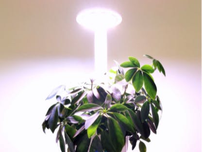
Plug in the power cord for your plant grower, wait for the light board to turn white, and unplug the power cord. Repeat this operation three times.
Congratulations! You have successfully prototyped a smart indoor garden. Backed by the Tuya IoT Platform, you can explore more projects that come in handy in real-life scenarios.


Comments