


Hardware components | ||||||
 |
| × | 2 | |||
 |
| × | 2 | |||
| × | 1 | ||||
| × | 1 | ||||
| × | 1 | ||||
| × | 1 | ||||
Software apps and online services | ||||||
| ||||||
| ||||||
| ||||||
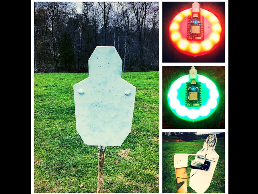
When shooting long range it is very important to have a spotter. The spotter is able to tell you many important things, but one of the most valuable is if you hit your target. Many times when shooting, the recoil of the firearm will prevent you from seeing the impact of your round. This makes it extremely hard to practice on your on. Also if you are a competition shooter many of the competitions have a time limit that the target must be hit within. If you go over that allotted time to make the shot then you will be disqualified. When practicing, trying to spot your own impacts, run a stop watch, and shoot can be very cumbersome. These are the problems that my team mate and I set out to fix with things you can buy on amazon for less than 100 dollars. The Blind Spotter is a two piece system that notifies the shooter if they hit their target or not with a red or green LED display. The half that attaches to the target is an accelerometer that attaches to the back of any steel target that is larger than 1 foot square. The other half is the display located next to the shooter. If the sensor on the target detects a sharp acceleration it will communicate with the display turning it green letting the shooter know that they hit the target. If the sensor doesn't detect a sharp acceleration then it will communicate with the display turning it red. This lets the shooter know that they either missed there target, or failed to hit it within their desired time limit.
Target SensorAbove is the sensor attached to the back side of the target. This is done with the strong magnet found in the parts list. The magnet allows the sensor to easily be attachable to any steel target. If the target is impacted, the swinging motion of the target will trigger the internet button's accelerometer sensor. This will publish a "Hit" turning the other internet button located next to the shooter, green. If there is no acceleration of the target detected with in the allotted time, programmable by the user, then the particle will publish a "Miss" and turn the shooters display red.
Target Set UpAbove in the first picture is the set up of the equipment on the target side. Below the first picture is a picture of the directional high gain WiFi antenna. This antenna allows the target to be placed at longer distances. Just as a rule of thumb, for every 6 dB of gain on the WiFi antenna the allowable distance of the signal will double. The antenna above is a 20 dB directional antenna which allowed us to double each incremental distance 3 times. Unfortunately, where the initial distance of the internet signal was so small it only allowed us to reach 250 meters in this demonstration.
Shooter's DisplayIn the picture above, the display located beside the shooter can be seen. This display allows the shooter to arm the internet button located on the back of the target. Once the button located in the 6 o'clock is pressed, it will turn the 11 neopixel LED's located on the display beside the shooter, white.
Once these LED's turn white, the particle located inside the display will publish an event called "ETA1min" which will tell the particle located on the back of the target to arm itself and be looking for acceleration. This is done by using the built in accelerometer located within the internet button. Every time the button is pressed on the display located beside the shooter, it will reset the value's being stored inside the particle and also calibrate the particle so that it can be used later for comparison. Once the value recorded by the accelerometer breaks a certain range, set in the code, the particle will publish an event called "Hit". Once this event is published the particle located beside the shooter will subscribe to this event and turn all the LED's green, indicating the shooter hit the target.
If the display turns green, the shooter can hit the same button (located at 6 o'clock) and reset the internet button on the target and also the display beside him or her. Once the button is pressed it will start an internal timer that is programmed by the shooter. At the end of the time, if no motion was detected, the particle located on the back of the target will publish an event called "Miss". Once this event is published the particle located beside the shooter will subscribe to this event and turn all the LED's red. This will let the shooter know that no motion has been detected and that he/she has missed.
Above is a graph of the data recorded in the project. In the graph when the shooter hits the target, it is recorded as a red dot having the value of 1. In the event that the shooter misses or runs out of time this will be represented as a red dot with a value of zero.
SchematicsAbove is a generic schematic of the internet button. The white cable at the top of the internet button is the power supply. The internet button used as the sensor on the target, was powered by an external power bank seen in the picture. The cable seen in the lower part of the picture is a mini UFL adapter so that the external antenna could be used.
Above is the top view of the internet button. As you can see the white squares at the outside circumference of the internet button is the LED's used in the project. Also to the right of the number 9 LED is the orientation of the accelerometer. The "y" axis was the only axis used in this experiment. Just above the number 6 LED on the Particle board, is the internal antenna seen as the white ceramic rectangle.
Above is the picture of the bottom side of the internet button. The 6 o'clock button that was referenced in the demonstration video above was used to reset the sensor. This button in this schematic is labeled as button 3. This was the only programmed button used in the shooter display.


Comments