


The project started in 2020, during Corona time. After some talks with a local company the idea was launched to develop a display system to visualize data from vehicles on a dashboard. To make it more universal, I investigated how I could make it more generic and I ordered some display modules from Nextion, Topway and Eastrising.
The module contained a graphical chip which was commonly used in a lot of demo projects and where demo code was already available. This was a perfect start to do some experiments with a ST Nucleo kit.
This resulted in the development of two proof of concepts where I used two 3, 4 inch TFT panels, one with resistive and one with capacitive touch interface. The Nucleo boards were mounted together with the Eastrising boards in two housings that were milled for the displays. There was a piëzo buzzer and a small gap to ensure that the sound could leave the enclosure.
I programmed a demo with 3 pages. The first page was an automotive application to drive signalization patterns in vans and trucks. The second demo was an industrial interface to show a progress bar, some data and alarms and the third one was a home automation system to put lamps on and off, switch on TV and mains plugs, change heating level and drive window shutters. I used Mbed which was a populair OS at that time. I made a combo with a Python script that sends serial data to a command interpreter to provide the neccesary feedback and interaction to let it behave like it was talking to a real hardware interface.
I presented this solution as an eye-catcher two times on Abbis Kortrijk, Belgium (2020 and 2022) and gathered some feedback. I heard that most applications need bigger screens and that flexibility is an important advantage. In the period 2023/2024 I had a meeting with some additional companies and they were interested in such kind of product.
Potential applications that came up during the different talks were:
- Home automation to visualize the level of water tank, shutters, etc.
- Presentation of syndic counters in appartments
- Interface of a fogger device for desinfecting the air
- Payment panel for an outdoor waste dump solution
- Touch panel for a cup collecting machine
I started to create a BOM list and I drawed a schematic to develop a prototype. I had to do a firmware upgrade to use a more recent microcontroller with more memory, a different touch panel controller and did a lot of hardware changes. I introduced the concept of a dual bord solution with a connector on the graphical board. It resulted in a new PCB. I printed a 3D enclosure to show the concept of a multi purpose console solution.
Because Mbed was unexpected abandoned by ARM, I had to perform additional work to get my MCU adopted in the new Mbed CE edition as one of the few and new project maintainers. The graphical board was called HMC-20 (Human Machine Controller - 2020) and the Application board got the name UAB-23 (User Application Board - 2023).
During the development, I invested in some devices (like vapor phase reflow oven, paste dispenser, etc.) to produce a Minimum Viable Product (MVP) for the HMC-20. A new demo application was introduced: The fogger interface with RTC and some different menu's accessed by a PIN code.
The HMC-20 is a flexible multi purpose, low cost HMI-interface board that is able to contain an add-on board to extend communication interfaces. The choice for a hardware splitup enables re-usability of the graphical board into multiple applications and reduces the cost in term of production quantities. Both boards communicate by means of a real time serial command interpreter, which makes it possible to quick-start creating demo's by implementing a Python script that communicates trough an FTDI-cable on the extension connector, before developing the real hardware.
The solution aims to reduce design complexity by abstracting the graphical part from the application part. The graphical layout can be determined by means of a Json file and a range of images (bmp/jpg) that are initially loaded from the SD-flash card into an on-board flash chip. The graphical controller can then read-out the chip directly with DMA (Direct Memory Access) to speedup image loading trough a fast speed quad SPI-bus. The memory chip is also used to save internal parameters like a pin code or a user setting.
Button actions are predefined as commands and are defined in the Json-file. It means that the graphical board also works independently when the interfaces are not the limiting factor. The graphical board has standard 5 digital inputs, 5 digital PWM enabled outputs, a USB-C 2.0 connector and a touch matrix connector. The USB interface is used to perform setting over a virtual serial port. There is also a RTC battery and a 24bit TFT RGB connector with touch controller interfaces for capacitive and resistive touch panels. Next to the graphical controller, there is an ultra low power STM-32U575 processor that is programmed trough an SWD-connector thats connects to a (clone) ST-Link V2 programmer. An internal boot loader enables programming signed and encrypted images over USB without using the programmer. The controller itself is read protected.
On the board there is also an auditive piëzo buzzer and a graphical font-chip that contains character maps for more than 150 languages. The power supply creates a stable internal 5VDC rail for its internals and the add-on board. A PWM-driver enables backlight dimming in the full range. The I/O voltage range is configurable by jumpers. The display is very bright up to 1000nit, which is useful in sunlight conditions.
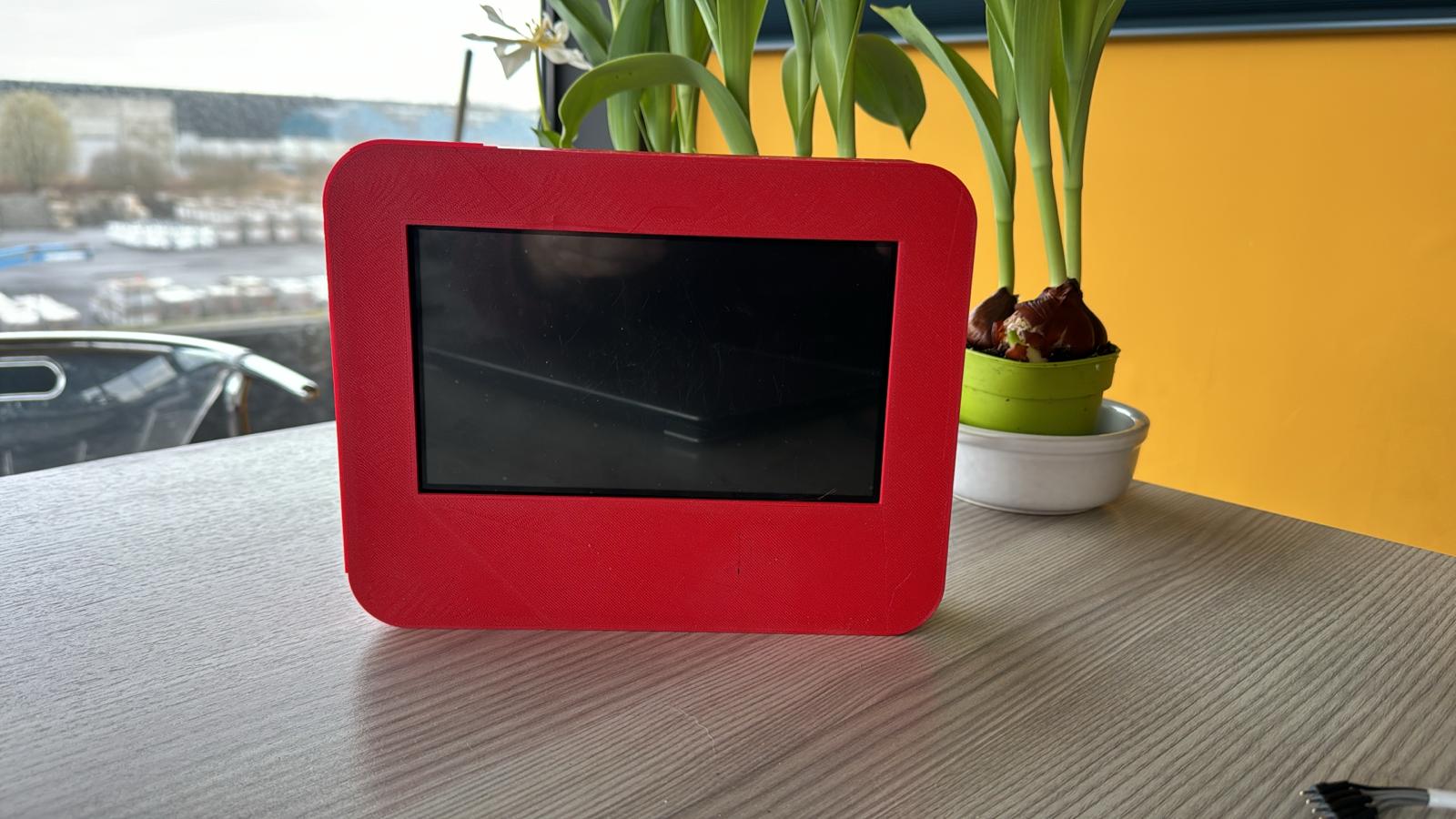
A red case has been 3D-printed with standard PLA that fits both boards to show the housing capabilities. It delivers a console look and feel that could be wall-mounted for applications in buildings, automotive environments or green-houses.
Currently there is a deisgn of a functional graphical board that contains some demo applications, together with a datasheet and a presentation. There is also a 3D printed enclosure which makes it possible to show a demo of a console when presenting the product in companies.
Because ARM stopped officially the Mbed project(1), it's important to make a shift towards other popular OS environments like Zephyr. The graphical interface is defined by Json files on the SD card that define an object tree. They are copied from the SD card into the flash with a serial command over the viurtual serial USB port. The images (jpg/bmp) are copied from the SD card to a flash memory and are refered in the layout files by means of strings. All interactions between buttons, widgets and IO are defined by sequential commands and are executed by the internal command interpreter.
There are some limitations because of the graphical chip. It's a Taiwanese controller with RGB interface which is already 10 a 15 years on the market. With the current application where the dual layer option is used, the resolution is limited to 800x480 pixels in 8bit RGB colors. There is also no possibility to use moving images unless you create animations with different fixed images. This chip is still available and you need to find the right ordering channels in Europe. It means that mounting the GPU must be done where the PCB's are produced. There are websites to order smaller quantities but orginality is never guaranteed.
There are currently more advanced graphical chips on the market like those of FTDI, Nuvoton, or using a STM32 with built-in MIPI interface. (2) However, this is a more complex solution where you need drivers and this needs additional investigation. The advantage should be that you can use more popular frameworks like Qt, but I see this more as a successor of the current product because it's a breaking change of the concept. It is also possible to test with the successors of the current chip with minimal firmware adaptation.
(1) https://os.mbed.com/blog/entry/Important-Update-on-Mbed/(2) https://www.st.com/en/evaluation-tools/stm32h747i-disco.html
Another point is the bootloader. The project mcu-boot(3) has been used and configured for use with STM32. I can sign and encrypt the images to avoid copy-cat en ensure integrity of the firmware. Mcu-boot is supporting Mbed and Zephyr as well.
Furthermore it is important to check for potential customers. Currently the project is considered to be OEM and targets integration as a sub-assembly of other devices. The purpose is to sell bigger volumes and provide a supporting service. But with some modifications it could become an end solution for a specific group of customers wich will make the product more market absorbable. For example for horticulture green-houses or as a console in buildings. The further evolution of the product will be dependent on what the potential customers are looking for. Further development in collaboration with the potential client will help to maximize the adoption degree. Such kind of activities are planned in the period 2026 to 2027.
There is a schematic of the add-on board (UAB-23) available that contains standard interfaces, but there is still some work to be done to bring this to a working prototype. The idea is that this part will become fully open source, so that the user can create his own application. It is also possible that the user develops his own PCB that fits on the HMC-20 and contains dedicated IO for the end application.


Comments