
Hardware components | ||||||
 |
| × | 1 | |||
 |
| × | 6 | |||
 |
| × | 2 | |||
 |
| × | 1 | |||
 |
| × | 1 | |||
 |
| × | 1 | |||
 |
| × | 1 | |||
Software apps and online services | ||||||
 |
| |||||
 |
| |||||
| ||||||
 |
| |||||
For lazy people like myself going to the switchboard to turn on the light is a big task. But what if the lights got turned on themselves whenever the room got dark and magically(read: automatically) got turned off when the room was bright? Cool, isn't it. This is exactly what is the aim of this project.
Using the Bolt Wifi module, I have made a circuit that can turn on/off the lights based on how dark/bright the room is. It checks the room's brightness every 10 seconds and depending on how bright the room is, the LED is turned on/off. If the state of the room is to be changed then I also get notified on my phone via a text message that the room is bright so the lights are being turned off or that the room us dark so the lights are being turned on. I have set upper and lower bounds on the usual brightness of the room that doesn't require lights to be turned on. If the brightness is more than the upper bound, the LED is turned off and if it is lower than the lower bound, the LED is turned on.
What if the room is bright enough for me to not turn on the lights but the intensity is lower than my set lower limit? Well, this is where the Google Assistant comes in handy. All I have to say is, "Ok Google, turn off the lights." It promptly does that.
Or when it is brighter than the upper bound yet a little more brightness would help, then I say to my Google Assistant to turn on the lights.
Steps:
Steps:Step 1: Hardware connections
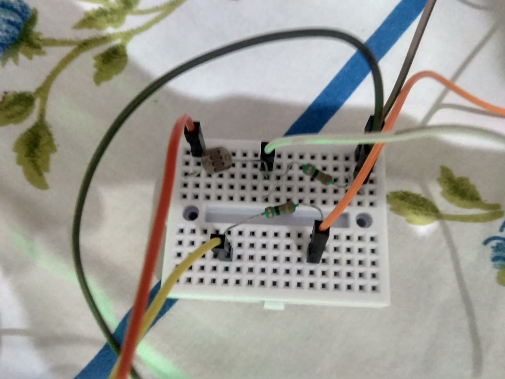
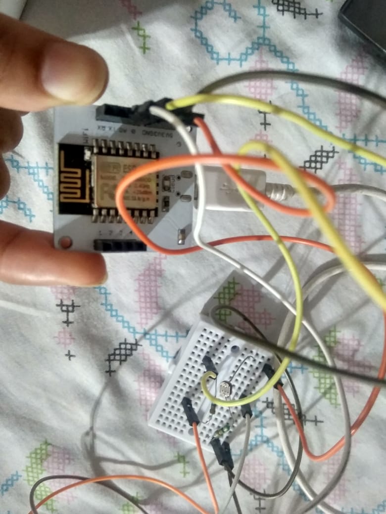
Take the breadboard, connect the LDR and one of the resistors in series. Take the other resistor and connect it to the breadboard separately from the LDR-resistor series connection.
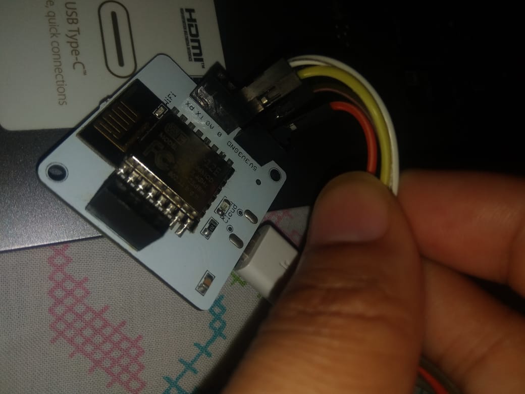
Then connect a jumper wire each to GND, 3V3, pin 0 and pin A0 of the Bolt device.
Now, connect these jumper wires as follows:
1. The one from GND to the other end of the resistor that is connected in series with the LDR, on the breadboard.
2. The one from A0 is to be connected to the point where we connected LDR and resistor in series.
3. The one from 3V3 to the other end of the LDR on the breadboard.
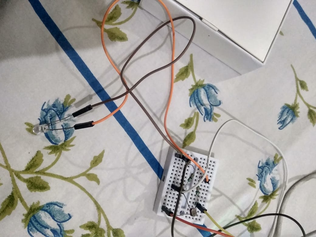
Now attach one jumper wire each to the two legs of the LED. The one emerging from the positive terminal(longer leg) to one end of the second resistor( which is not in series with LDR). The jumper wire from the negative leg of the LED(shorter leg) goes in series with the GND connection we made before.
Finally, connect pin 0 wire to the other end of the second resistor( which is not in series with LDR).
Add an image
Delete this image
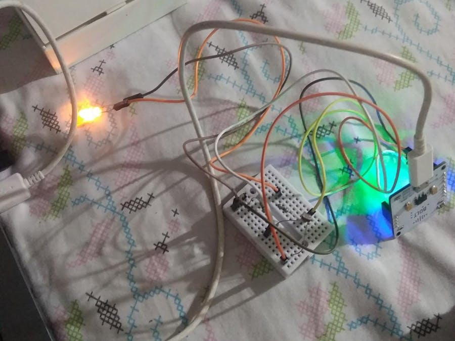
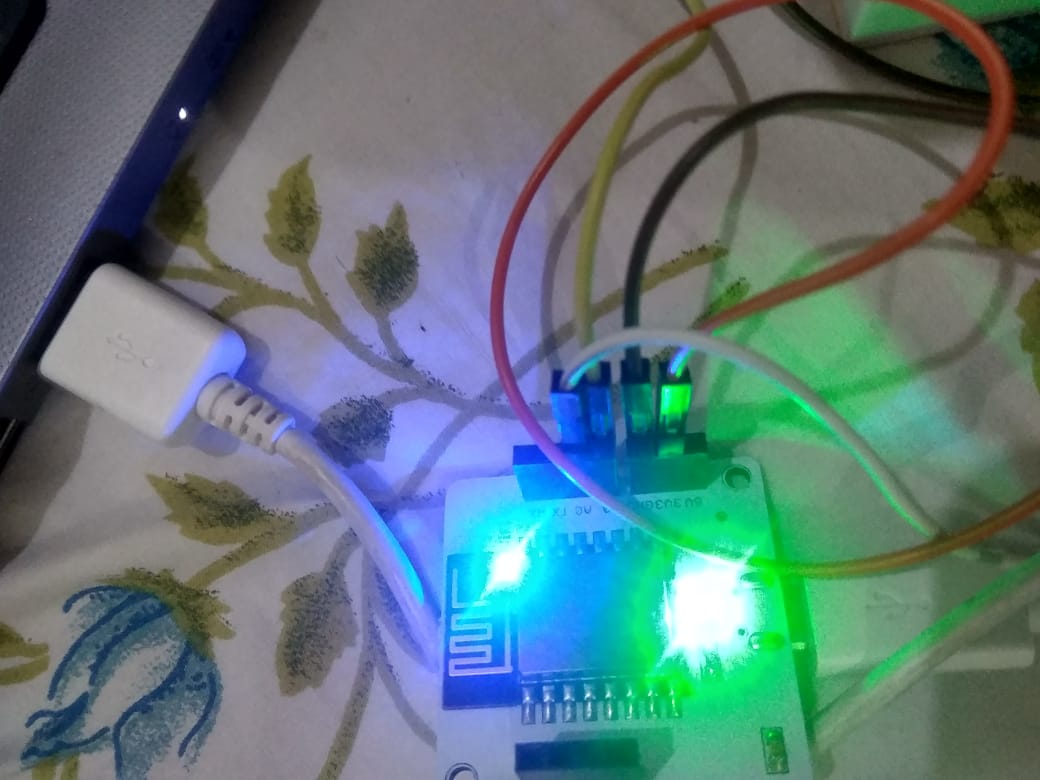
Connect the Bolt Wifi module to a power source via USB cable, and voila! The hardware configuration is complete!
Add an image
Delete this image
Step 2: Creating a configuration file
We will create a file which would contain all the necessary details to the resources we'd use, for instance, the device ID and API key of the Bolt module.
You will find your API key and device ID on your Bolt cloud account.
Then create an account on Twilio which is a 3rd party SMS service provider. Turn off DND on your phone, if enabled, because Twilio can't send SMSs to numbers which have DND enabled.
Follow these steps to create your Twilio account:
1. Open https://www.twilio.com/
2. Click on Sign Up
3. Fill the necessary details up.
4. You'd then have to verify your email by clicking on the link that is sent to your email.
5. After email verification, you'd have to get your number on which you want to receive messages verified. Enter it by selecting your country(in my case, India).
5. Next, you're to select under Products tab, Programmable SMS and Phone numbers.
6. Once done, click on Continue. Name your project. Click on Continue.
7. Click on Skip this step when asked to invite a Teammate.
8. The project would be created now, click on Project Info to view your account credentials.
9. You'd need to copy the Account SID and the Auth Token( it is hidden, click on View, to see it).
10. From the drop-down menu choose "Programmable SMS". Now click on "Get Started" which will generate your number.
11. Click on "Get a number" button. On the pop-up that appears, click on "Choose this number". Then a pop-up will appear which will have the final number, copy it.
Now, this is it for Twilio.
Note: if you are trying this step out after 9 pm IST, you won't get the messages.
Launch your Ubuntu server, whether the one you access via puTTy or VirtualBox or VMware.
Now create a file using the command below:
sudo nano conf.py
Values for the variables used in conf.py:
SSID= the Twilio Account SID
Auth_Token= auth token from Twilio
From_no= Number generated using Twilio
To_no= number you linked your Twilio to get messages
API_key= Bolt API key from Bolt Cloud
Device_ID= Device ID of your Bolt module, gotten from Bolt cloud.
Press CTRL+X, press Y and then Enter.
The configuration file is the link between your python file and bolt, Twilio accounts.
Now we'd create the python file which will bring the project alive.
Step 3: Python file
Code description:
We begin with importing our configuration file, the modules time and json. Along with these, the boltiot python library's Sms and Bolt modules have been imported.
Next, I've set a lower limit to the usual brightness in my room and an upper limit to the same.
The API key and device ID are passed as arguments to the Bolt function and the result is stored in mybolt variable.
The Twilio details are passed as arguments to Sms function and stored in the variable SMS.
a variable flag is initialised to check for the LED's status: On or Off. If the status is 0 i.e. off, the flag is made zero, if status = 1 i.e. On, flag =1.
Now we enter into an infinite loop wherein we'd check the sensor to decide whether to turn the LED on or off.
If the sensor's value is higher than the upper limit and the LED is in On state, we request the Twilio server to send a message notifying the user on their phone that the room is bright enough, therefore the light should be turned off.
Consequently, the following code turns the light off as well( using the digitalWrite()) and resets the flag. We also record the response received from Twilio.
Otherwise, if the sensor's value is lesser than the lower limit and the flag =0 i.e. LED is off, we request the Twilio server to send a message on our phone that the room is dark so the lights are being turned on.
Consequently, the code following this request code turns the light on( using the digitalWrite()) and sets the flag. We also recorded the response received from Twilio.
In case of an error, the code jumps into the except block and the error details are printed.
The last element in the loop is setting the timer i.e. collecting the sensor data after 10 seconds have elapsed since the last recording of the sensor's value.
Output on the terminal is:
Alert messages on phone:
Step 4:Connecting the system to Google Assistant
First, we need to note/ copy the GPIO command that makes the Bolt module turn the light on and off.
Go to the Bolt Cloud. Scroll to the Docs section on the main page.
On the Docs page, go to API documentation, from there go to GPIO commands wherein you have to select the Write Digital Output tab.
The command to write digital output is:
https://cloud.boltiot.com/remote/YOUR_API_KEY_HERE/digitalWrite?pin=0&state=HIGH&deviceName=DEVICE_ID_HERE
eg:
https://cloud.boltiot.com/remote/123456789/digitalWrite?pin=0&state=HIGH&deviceName=BOLT1234567
This command will turn the LED On.
To turn the LED off, simply replace the value of the state attribute to LOW in the aforementioned URL.
Save these two links.
Now, we'd integrate our Bolt module with Google Assistant using IFTTT and Webhooks.
Follow these steps:
1. Create an account on IFTTT using the Gmail account to which your Google Assistant is linked.
www.ifttt.com
2.Then to create a new applet by going on the URL:
ifttt.com/create
3. Click on +This
4. Choose Google Assistant> Say a simple phrase
5. Type in the phrase that will trigger the action, specify the trigger phrase in several ways to make it easier to invoke the GA.
6. Type in the response that GA should say when it acknowledges your request.
7. Click on Create trigger.
8. Now, click on '+That'.
9. Choose Webhooks.
10. Select make a web request, it will take you to another page. On the new page, enter the API URL to turn the LED on that you saved from Documentation on Bolt Cloud.
11. Choose the 'GET' method. Choose application/json from the drop-down as your content type.
12. Click on Create action. It will take you to a page where you can review it, if you're satisfied and sure, click on Finish.
Repeat the above process from step 2 to 12 to turn the LED off. Remember to use the URL for turning off the LED this time.
And, that's it! Now, try saying 'Ok Google' to your GA and say one of your trigger phrases, it would reply with the response phrase and voila! The LED would behave likewise!
Add an image
Delete this image
Note: Keep the LDR away from the LED source, so that the LED's light doesn't meddle with your program.


Comments