


Hardware components | ||||||
 |
| × | 1 | |||
 |
| × | 1 | |||
 |
| × | 1 | |||
 |
| × | 1 | |||
 |
| × | 1 | |||
 |
| × | 1 | |||
| × | 1 | ||||
 |
| × | 1 | |||
 |
| × | 1 | |||
| × | 1 | ||||
| × | 1 | ||||
Software apps and online services | ||||||
 |
| |||||
Hand tools and fabrication machines | ||||||
 |
| |||||
 |
| |||||
 |
| |||||
 |
| |||||
 |
| |||||
This project aims to do these following things: Be creative, cheap, and most importantly fun!
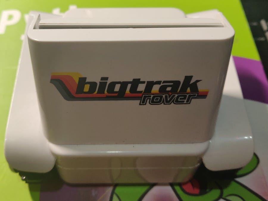
IntroAs a child I was always in awe at the Bigtrak toys of the 80's. The keypad that you had to use to program them and the design of what reminded me of a futuristic mining vehicle.
So it came about last year when I was Christmas shopping that I happened upon the Bigtrak Rover, at the time it was discounted to 7£ sterling or around 9 US dollars.
I had hoped it would be a hit with the kids, which it wasn't. especially when they realized they would have to give up their phone to use it...
And so it sat for nearly a year, hidden away in the depths, lost to the human eye...
THEN! I found it randomly as I was cleaning out a closet, defunct of its battery cover and batteries, it sat pleading for rescue...
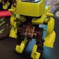
The BuildIn taking it apart I realized that it is a fairly well made toy (apart from the PCB). Durable body and seemingly robust ''tracks''. It operate on the principle of light generated from a smartphone via the Bigtrak Rover App. This light or is used to control the device.
I removed all the electronics while leaving the mechanical pieces intact, for possible future uses.
I decided to use an Arduino nano because of its small size and as I already had one available. You could also use an Arduino pro-mini, or other similar form factor micro controller. Perhaps even an STM32 breakout board...
I did solder together a breakout board for the Arduino nano and it involved a fair bit of soldering including dedicated pin traces for the servo control. If your new to soldering or prefer not to then the same can be accomplished using a half-size breadboard.
The motor controller I chose was the MX1616 2.5A Max current board, this was due to size, cost (US $0.55), and I already had one from a previous project.
The motors are also very tiny and make use of a gearbox, cleverly designed in my opinion... Although the wires can be tricky to solder.
The Bigtrak incorporates a battery holder as do most small battery powered toys, this holds 3 AA size 1.5 volt batteries. I decided to use this as a means of power for the entire system, although it does not create 5 volts or higher it seems to work fine and the arduino board seems to be tolerant of the ''raw'' voltage. Perhaps it's even a little under-powered.
Feedback & Updates
Please leave a comments, let me know what help you may need :)
I will be uploading the Arduino code and circuit schematic soon. In the mean time the wiring of the MX1616 motor driver is very similar to that of the popular L298.
In this example the pin-out is as follows:
HC-SR04 Connections:
Arduino Pin A1 to HC-SR04 ''Trig''
Arduino Pin A2 to HC-SR04 ''Echo''
HC-SR04 ''VCC'' and ''GND'' go to power and ground respectively
MX1616 Motor Driver Connections:
Arduino Pin D4 to INT2 RIGHT FORWARD ENABLE
Arduino Pin D5 to INT1 RIGHT REVERSE ENABLE
Arduino Pin D7 to INT3 LEFT FORWARD ENABLE
Arduino Pin D6 to INT4 LEFT REVERSE ENABLE


Comments