

Hardware components | ||||||
 |
| × | 1 | |||
 |
| × | 1 | |||
 |
| × | 1 | |||
 |
| × | 2 | |||
 |
| × | 1 | |||
 |
| × | 1 | |||
 |
| × | 1 | |||
Software apps and online services | ||||||
 |
| |||||
| ||||||
 |
| |||||
Nijel, one of our friends who works in a Pharmaceutical company. These days due to the COVID pandemic situation Nijel is working hard tirelessly, he has putted his day and night hardship into the work and research to find the cure for the corona virus.
As in the entire lockdown situation, he was performing his researches from home and consulting with the staff through online mediums. But for a few days, as the lockdown lifted he got too disturbed, he is suffering through tremendous issues like.
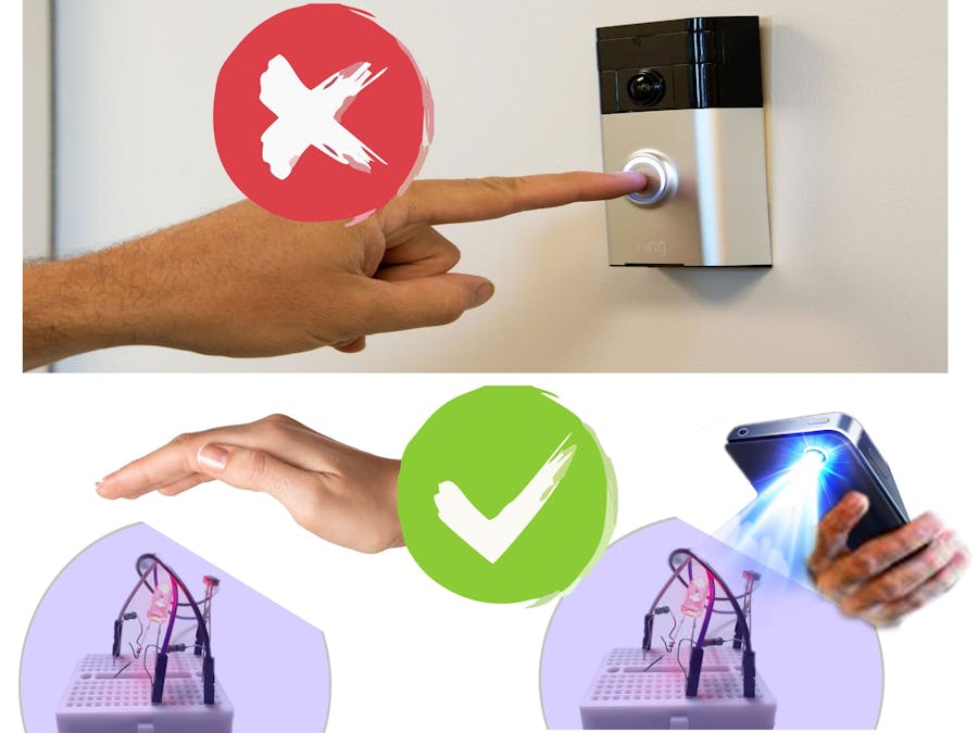
He lives in a bad neighborhood where kids used to play with the doorbells as well as in his house, Many peoples are coming from outside like his relatives, pizza delivery boy, and even he used to go out for grocery shopping but in order to ask someone to open the gate they all have to touch (press) the doorbell. This not only disturbs him concentrating on his research but also made him worry in a protective way about the spread of the corona virus through the doorbell.
As he was familiar with the Bolt IoT and had knowledge about Machine learning he decided to build something which not only solves his disturbance due to doorbell noise but also presents a protective measure in alternative to the doorbell and keeps his doorbell untouched.
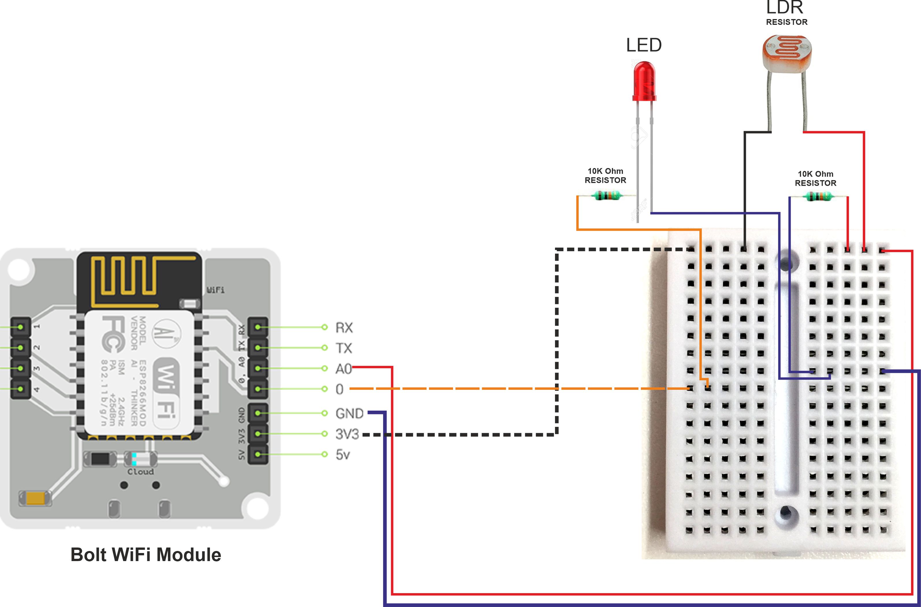
Hardware SetupNote:Make sure the Bolt module is not powered on while making connections and Double-check all connections before turning it on.
Firstly we will connect breadboard with Bolt IoT WiFi Module pins with the help of Jumper Wires. Here we are going to use only four pins:
- 3v3 Pin
- A0 Pin
- GND Pin
- 0 Pin
As in the case of LDR and resistor, there is no positive or negative end for them. So we will Insert one leg of the LDR into the Bolt Module's 3v3 Pin-connected row of the breadboard and other lead into the A0 pin connected row.
Now, Insert one leg of the 10k Ohm resistor into the GND pin-connected row and another leg of the resistor into the A0 pin-connected row.
Warning!! Make sure that at no point do the 3.3V and GND pins or wires coming out of them touch each other. If you short power to Ground without a resistor even accidentally, the current drawn might be high enough to destroy the Bolt module
Thus, we are effectively measuring the voltage across the 10k Ohm Resistor it's time to connect Alert System.
Now we will connect LED for Alert System, As we have already connect required pin to breadboard,
Connecting the LED to the Bolt
Take one leg of the resistor and wrap it around the longer leg of the LED i.e positive leg.
Now, Insert the negative leg of the LED into the GND Pin-connected row of the breadboard. and Insert the other leg of the resistor in digital pin 0 connected row of the breadboard.
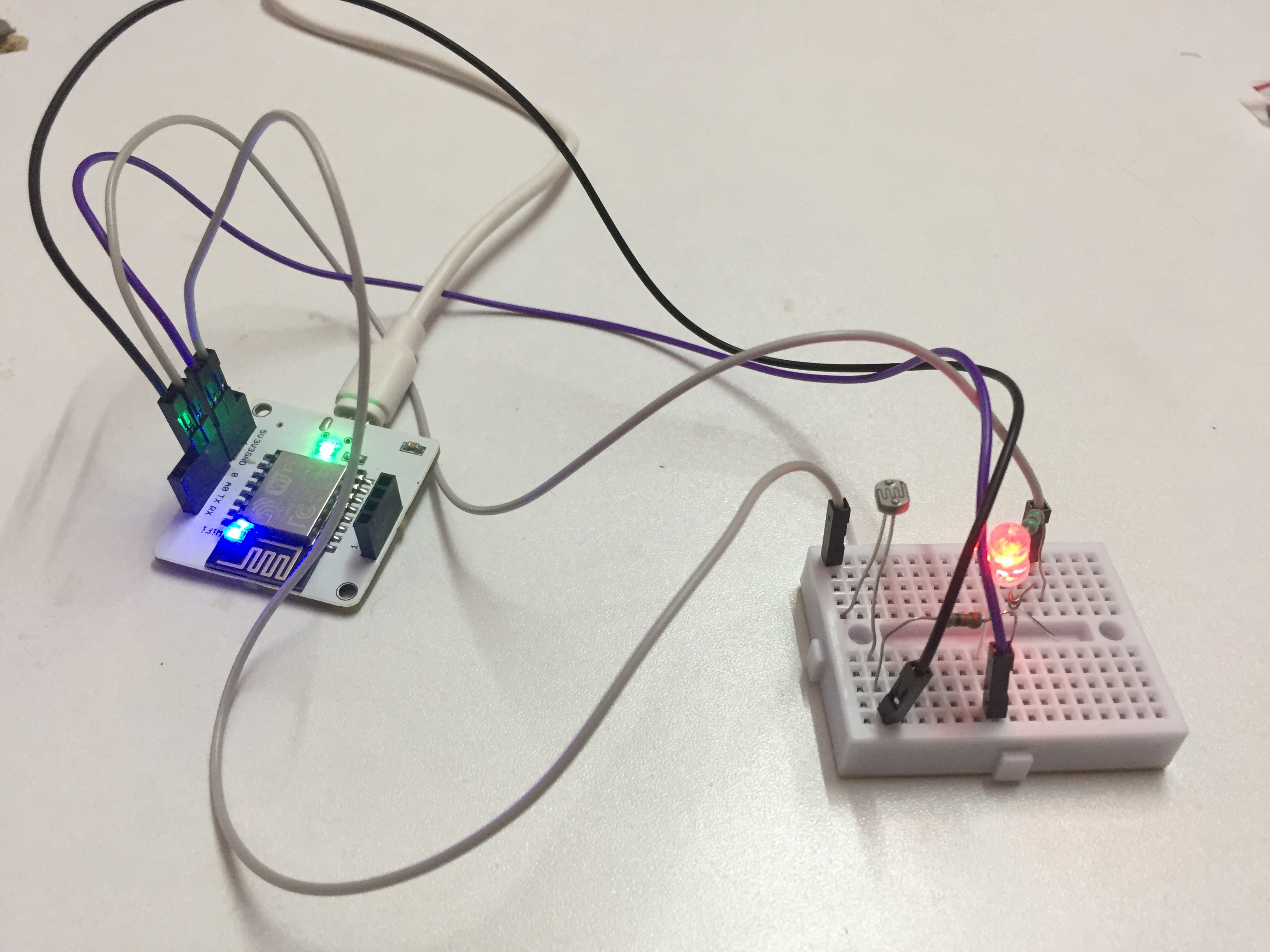
And the final circuit should look like the image.
Now we have all done with the connection, its time to safely power on the Bolt module.
As the aim of the project is to send SMS alert when someone comes on the front of the gate and brings his/her hand or flashes a light on the LDR, we will be using Twilio for this purpose to send alert SMS.
Twilio is a third-party SMS functionality provider. It is a cloud communications platform as a service (PaaS) company. Twilio allows software developers to programmatically make and receive phone calls and also send and receive text messages using its web service APIs.
1. Twilio Account Setup :
Step 1: Open https://www.twilio.com/ in a browser.
Step 2: Click on Get a Free API Key button to sign up.
Step 3: Fill all the necessary details in the SIGN UP form. Below is the screenshot of the filled sign up form.
Step 4: To verify they will ask for your phone number. Choose India as an option in the dropdown and then enter your phone number.
Step 5: Click on "Products" as shown on the screen below,
Step 6: Now enable the SMS services by clicking on two checkboxes for Programmable SMS and Phone Numbers as shown below.
Once you have done this, scroll to the bottom of the screen and click on "Continue".
Step 7: Now, you will need to give a name for your project. I have given the name as My Project. Click on "Continue" once you have entered the project name.
Step 8: Click on "Skip this step" when it asks you to Invite a Teammate.
Step 9: Your project should be created at this point. Click on "Project Info" to view the account credentials which is required for your projects.
Step 10: You can view the Account SID and Auth token on this page. The Auth token is not visible by default, you can click on "view" button to make the Auth token visible as shown below. Copy both and save them somewhere securely.
Step 11: From the drop-down menu, choose "Programmable SMS". Now click on Get Started button to generate phone number.
Step 12: Click on Get a number button.
Step 13: Then a popup will appear. Click on Choose this number button.
Step 14: Then a popup will appear which will have the final number. Copy this number and save to notepad for future references.
That's it. Now we have successfully created the account on Twilio.
2. LED Control Setup
Go to cloud.boltiot.com and create a new product.
While creating the product, choose product type as Output Device and interface type as GPIO.
After creating the product, select the created product and then click on the configure icon.
Now, Move to the code tab
and write the following code to control the LED.
<!DOCTYPE html>
<html>
<head>
<title>Bolt IoT Platform</title>
<script type="text/javascript" src="https://cloud.boltiot.com/static/js/boltCommands.js"></script>
<script>
setKey('{{ApiKey}}','{{Name}}');
</script>
</head>
<body>
<center>
<button onclick="digitalWrite(0, 'HIGH');">ON</button>
<button onclick="digitalWrite(0, 'LOW');">OFF</button>
</center>
</body>
</html>
Now save and exit the configuration and link this product with the Bolt Module.
and select the Device.
As we have created our LED product, configured it and linked it to our Bolt module, we will open Bolt mobile app and can see the below option by selecting our device.
where on click "ON" button, it will turn the LED on. Similarly, clicking on "OFF" button will turn LED off.
As we have done with the Hardware and Software setup, with the help of Code (which can be found below) we will store the sensor value and compute z-score and alert system.
For the coding part we will use Bolt Python library along with json, time, math, statistics, and boltiot library to find out whether someone is at the front door and wanted us to open the gate, and send an SMS when this happens. We are also going to write a python code that will use z-score analysis to find out the Anomality.
Below I have Demonstrated and explained the applied example of the above-stated project.
Understanding the Doorbell Alert SystemNow as we have completed hardware and software setup, now power up the Bolt module and ensure that it is connected to the Bolt Cloud. After running the python code, it will initially start printing the following.
After about 200 seconds (10 seconds delay with a frame size of 20, which can be customized by changing frame size value in conf.py file), the system will start printing the light intensity values, as per the following image.
We can now try moving hand or a light source close to the LDR. If we start from far away and move the hand close or away to the LDR slowly, the system will not send an alert. Similarly, if we move the light source close or away to the LDR slowly no alert will be sent. But if we suddenly move our hand or a light source close to the LDR, then the system will print the following
and will turn LED ON.
as well as sends an alert SMS saying "Someone is Standing on the door. Open the gate".
So, what is happening here?
Well in this project, we are using the Z-score algorithm to dynamically change the bounds at which an alert is sent.
So when we move our hand or the light source close to or away from the LDR slowly, the bounds also start changing slowly.
But when we move our hand or the light source close to or away from the LDR very fast, the bounds do not change fast enough, and the system detects an anomaly and turn the LED on and sends an SMS alert.
Note: we can tune the system by changing the FRAME_SIZE and MUL_FACTOR values in the conf.py file.
Doorbell Alert System Working Principal:- It will ask people to bring their hand/palm closer to the LDR sensor or flashlight on the LDR sensor then it will fetch the latest sensor value from the Bolt device.
- Store the sensor value in a list, that will be used for computing z-score.
- Compute the z-score and upper and lower threshold bounds for normal and anomalous readings.
- Check if the sensor reading is within the range for normal readings. which can be customized by changing FRAME_SIZE and MUL_FACTOR value.
- If it is not in range, send the SMS and turn LED pin High.
- Wait for 10 seconds.
- Repeat from point 1.
Well throughout the day, the light setting on the LDR sensor will change with the rising and setting of the sun. This change will be slow, and the bounds for the system will change to match this change. But when someone will bring his/her hand close to the LDR sensor or flashlight on the LDR sensor, the intensity of light on LDR sensor will change suddenly. Because of this, the system will detect an anomaly and quickly turn LED light on as well as send an SMS alert that there is someone standing on the door.
Here, both the problem of Nijel get solved:
- As the code function has
time.sleep()function using which Nigel can set the duration of the alert, as normally people used to press the doorbell for quite a long time until someone arrives to open the door, here in this case by using thetime.sleep()function Nijal can adjust in what duration or the interval of time he will be ok to receive doorbell alert. It also reduces the Noise Pollution and for alerting it turns the LED on which can be turned off using the BOLT Cloud Android Application. - And as the people coming to his house are asked to put their hand close to the LDR sensor or flashlight on it, the doorbell will be untouched. And Nijal can rest assure about the spread of Corona Virus.


Comments