
Hardware components | ||||||
 |
| × | 1 | |||
 |
| × | 1 | |||
Software apps and online services | ||||||
 |
| |||||
 |
| |||||
Hand tools and fabrication machines | ||||||
 |
| |||||
 |
| |||||
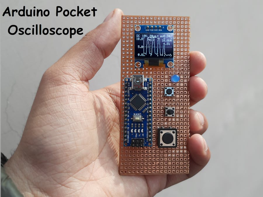
Previously, I posted a tutorial on Raspberry Pi-Pico Oscilloscope. And that was a great success. Keeping portable options in mind, I found this pretty mini oscilloscope between thousands of pages of a Japanese website. We are using a mini-OLED 128X64 to display the signal waveform, Frequency, duty cycle. 4 tactile buttons are used to change the modes, Volts/Divisions, and time/Divisions. So, I tried this, and the results are here.
Note* This project is only for educational purposes and shows the capabilities of a 16Mhz 8-bit microcontroller board. This MCU Can support frequencies below 50KHz, so it can’t be applicable for commercial and professional uses. That way, the project can also be entitled POOR MAN OSCILLOSCOPE for me.
Arduino Nano/Uno:Both the boards have the same 8-bit Atmega328p microcontroller to use any of them. This tutorial uses I2C communication to print the readings on an OLED display. Our microcontroller has 6-channel 10-bit ADC, 13 digital I/O pins, and an 8Mhz internal clock.
That's why I tried the project on breadboard first. I want to know the plus/minus points of this oscilloscope. This project is sponsored By JLCPCB, Pcb, code and circuit diagram to this project is given below. Download all Gerber file from here and Quote for PCB on JLCPCB just in $2, On first sign-up from here you will get worth $30 coupons to order PCB.
For PC: https://jlcpcb.com/SSRor mobile phone: http://m.jlcpcb.com/ssi
Features:- Single-channel -20Khz bandwidth
- Onscreen- Volt/Div and Time/Div
- Duty cycle monitoring
- Small 0.96-inch I2C
- AC/DC measurements option
- Mode changing, Hold state features
- Low battery consumption
- Portable and pocket-sized
0.96-inch OLED display with I2C function comes with two different models, SSD1306 and SH1106, to change the code as per requirements. We have to uncomment which version of LCD we are using in this project.
Components used:- Arduino Nano
- 128X64 OLED display
- 100k, 10k, 820k, 510k, 12k resistors
- 100nf, 7pf, 1uf ceramic disc capacitors
- Tactile switch x4
- Breadboard
- Connecting wires
After making all the connections, this oscilloscope can be powered by a 5v @100mA power supply or 3.7 volt Battery. Significantly fewer external components are used in this project; also, it supports several actions. Here MODE button is to select the volt/div, time/div, AC/DC, and 180* wave settings.
After selecting the Mode, we can either increase the value or decrease per wave format. For Volts/divisions: This oscilloscope supports a division from 0.2volts to 50volts.
For Time/Div: Code is modified to display small divisions in microseconds, 1.56 microseconds to 200milli-seconds.
- With 50Hz sine wave:
I tried to hook upthis oscilloscope directly with Step down transformer AC signal and here are the results:
- With 300HZ sine wave:
- With triangular wave:
- With rectangular wave:
- With sawtooth wave:
OLED display SSD1306, SH1106, Fix_fft and EEPROM libraries are available in Arduino Mange library section. From here you can download as per your needs.
Code is quite bit long, so we added comments on all lines so that you can understand this. Code version 1.1
// Follow us on Hackster, Hackaday and the Instructables.
//Please First uncomment/comment the oled driver lines, which you are using
//Circuitkicker.com -- Sagar saini --sainisagar7294
#include <Wire.h>
#include <Adafruit_GFX.h>
#include <Adafruit_SSD1306.h>
//#include <Adafruit_SH1106.h> // https://github.com/wonho-maker/Adafruit_SH1106
#include <EEPROM.h>
#define SCREEN_WIDTH 128 // OLED display width
#define SCREEN_HEIGHT 64 // OLED display height
#define REC_LENG 200 // size of wave data buffer
#define DISP_LENG 100 // size of display data
#define MIN_TRIG_SWING 5 // minimum trigger swing.(Display "Unsync" if swing smaller than this value
#define DOTS_DIV 25
// Declaration for an SSD1306 display connected to I2C (SDA, SCL pins)
#define OLED_RESET -1 // Reset pin # (or -1 if sharing Arduino reset pin)
Adafruit_SSD1306 oled(SCREEN_WIDTH, SCREEN_HEIGHT, &Wire, OLED_RESET); // device name is oled
//Adafruit_SH1106 oled(OLED_RESET); // use this when SH1106
#define R_12k 4 // 12k ohm
#define R_820k 16 // 820k ohm for AC low range
#define R_82k 17 // 82k omm for AC Hi range
// Range name table (those are stored in flash memory)
const char vRangeName[10][5] PROGMEM = {"A50V", "A 5V", " 50V", " 20V", " 10V", " 5V", " 2V", " 1V", "0.5V", "0.2V"}; // Vertical display character (number of characters including \ 0 is required)
const char * const vstring_table[] PROGMEM = {vRangeName[0], vRangeName[1], vRangeName[2], vRangeName[3], vRangeName[4], vRangeName[5], vRangeName[6], vRangeName[7], vRangeName[8], vRangeName[9]};
const char hRangeName[22][6] PROGMEM = {"200ms", "100ms", " 50ms", " 20ms", " 10ms", " 5ms", " 2ms", " 1ms", "500us", "200us", "100us", " 50us", " 81us", " 41us", " 20us", "156us", " 78us", " 31us", "15.6u", "7.8us", "3.1us", "1.56u"}; // Hrizontal display characters
const char * const hstring_table[] PROGMEM = {hRangeName[0], hRangeName[1], hRangeName[2], hRangeName[3], hRangeName[4], hRangeName[5], hRangeName[6], hRangeName[7], hRangeName[8], hRangeName[9],
hRangeName[10], hRangeName[11], hRangeName[12], hRangeName[13], hRangeName[14], hRangeName[15], hRangeName[16], hRangeName[17], hRangeName[18], hRangeName[19], hRangeName[20], hRangeName[21]};
const float hRangeValue[] PROGMEM = { 0.2, 0.1, 0.05, 0.02, 0.01, 0.005, 0.002, 0.001, 0.5e-3, 0.2e-3, 0.2e-3, 0.2e-3, 81.3e-6, 81.3e-6, 81.3e-6, 156.25e-6, 78.125e-6, 31.25e-6, 15.625e-6, 7.8125e-6, 3.125e-6, 1.5625e-6}; // record speed in second. ( = 25pix on screen) this value used for freq calc.
int waveBuff[REC_LENG]; // wave form buffer (RAM remaining capacity is barely)
char chrBuff[8]; // display string buffer
char hScale[] = "xxxAs"; // horizontal scale character
char vScale[] = "xxxx"; // vartical scale
float lsb5V = 0.00563965; // (5V)sensivity coefficient of 5V range. std=0.00563965 1.1*630/(1024*120)
float lsb50V = 0.0512939; // (50V)sensivity coefficient of 50V range. std=0.0512939 1.1*520.91/(1024*10.91)
float lsb5Vac = 0.00630776; // std=0.00630776 V/LSB
float lsb50Vac = 0.0579751; // std=0.0579751 V/LSB
volatile int vRange; // V-range number 2:50V, 3:20V, 4:10V, 5:5V, 6:2V, 7:1V, 8:0.5V, 9:0.2V
volatile int hRange; // H-range nubmer 0:200ms, 1:100ms, 2:50ms, 3:20ms, 4:10ms, 5:5ms, 6;2ms, 7:1ms, 8:500us, 9:200us, 10:100us, 11:50us, 12:
volatile int trigD; // trigger slope flag, 0:positive 1:negative
volatile int scopeP; // operation scope position number. 0:Veratical, 1:Hrizontal, 2:Trigger slope, 3:DC/AC/FFT
volatile boolean hold = false; // hold flag
volatile boolean switchPushed = false; // flag of switch pusshed !
volatile int saveTimer; // remaining time for saving EEPROM
int timeExec; // approx. execution time of current range setting (ms)
int dataMin; // buffer minimum value (smallest=0)
int dataMax; // maximum value (largest=1023)
int dataAve; // 10 x average value (use 10x value to keep accuracy. so, max=10230)
int dataRms; // 10x rms. value
int rangeMax; // buffer value to graph full swing
int rangeMin; // buffer value of graph botto
int rangeMaxDisp; // display value of max. (100x value)
int rangeMinDisp; // display value if min.
int trigP; // trigger position pointer on data buffer
boolean trigSync; // flag of trigger detected
int att10x; // 10x attenuator ON (effective when 1)
int inMode; // 0=DC+, 1=DC+-, 2=AC
int offset5Vac;
int offset50Vac;
float waveFreq; // frequency (Hz)
float waveDuty; // duty ratio (%)
#include <fix_fft.h>
#define FFT_N 128
volatile boolean fftMode = false; // FFT mode false:Wave, true:FFT
void setup() {
pinMode(2, INPUT_PULLUP); // reserve (button press interrupt (int.0 IRQ))
pinMode(3, OUTPUT); // PWM for trigger level
pinMode(R_12k, INPUT); // pin4 1/10 attenuator(Off=High-Z, Enable=Output Low)
pinMode(5, INPUT_PULLUP); // FFT mode
pinMode(7, INPUT_PULLUP); // AC mode
pinMode(8, INPUT_PULLUP); // Select button
pinMode(9, INPUT_PULLUP); // Up
pinMode(10, INPUT_PULLUP); // Calibration pulse output
pinMode(11, INPUT_PULLUP); // Hold
pinMode(12, INPUT_PULLUP); // Down
pinMode(13, OUTPUT); // LED
pinMode(R_820k, INPUT); // A2
pinMode(R_82k, INPUT); // A3
DIDR0 = 0x0f; // disable digital input buffer of A0-A3
oled.begin(SSD1306_SWITCHCAPVCC, 0x3C); // select 3C or 3D (set your OLED I2C address)
// oled.begin(SH1106_SWITCHCAPVCC, 0x3C); // use this when SH1106
auxFunctions(); // Voltage measure (never return)
loadEEPROM(); // read last settings from EEPROM
#define REFERENCE_INTERNAL
#ifdef REFERENCE_INTERNAL
analogReference(INTERNAL); // ADC full scale = 1.1V
trigger_level(26); // PWM triger level 0.5V for ET
#else
analogReference(DEFAULT); // ADC full scale = 5.0V
trigger_level(128); // PWM triger level 2.5V for ET
#endif
(void) analogRead(0); // dummy read to select A0 and reference
#ifdef USE_PIN2IRQ
attachInterrupt(0, pin2IRQ, FALLING); // activate IRQ at falling edge mode
#else
PCMSK0 = _BV(PCINT4) | _BV(PCINT3) | _BV(PCINT1) | _BV(PCINT0); // D8,D9,D12 pin change interrupt
PCICR = _BV(PCIE0); // enable interrupt from PCIE0 group
#endif
startScreen(); // display start message
}
void loop() {
if (hRange < 15) pulse(); // calibration pulse is for realtime sampling only
setInputOffset(); // coupling mode set(AC/DC)
setConditions(); // set measurment conditions
digitalWrite(13, HIGH); // flash LED
readWave(); // read wave form and store into buffer memory
digitalWrite(13, LOW); // stop LED
setConditions(); // set measurment conditions again (reflect change during measure)
dataAnalize(); // analize data
writeCommonImage(); // write fixed screen image (2.6ms)
plotData(); // plot waveform (10-18ms)
dispInf(); // display information (6.5-8.5ms)
oled.display(); // send screen buffer to OLED (37ms)
saveEEPROM(); // save settings to EEPROM if necessary
while (hold == true) { // wait if Hold flag ON
dispHold();
if (inMode > 0) { // if DC mode,
if (acZero() == 1) { // if offset adj. executed
scopeP = 0; // scope position to vartical
hold = false; // cancel hold
}
delay(10);
} //
}
}
int acZero() { // cancel AC renge offset
if (digitalRead(8) == LOW) { // if select pushed
if (vRange >= 5) { // = 5V or less
offset5Vac = dataAve / 10; // adjust the offset
} else { // range more than 5V
offset50Vac = dataAve / 10; // adjust the offset
}
saveEEPROM(); //
return 1; // adjusted
}
return 0; // no adjust
}
void setInputOffset() { // set offset circuit
if (inMode >= 1) { // if AC mode
if (att10x == 1) { // 10X-att enabled
pull5V(R_82k); // ‹ pull 5V by 82k
hiZ(R_820k);
} else { // 10X-att disable
hiZ(R_82k);
pull5V(R_820k); // pull 5V by 820k
}
} else { // DC mode
hiZ(R_820k); // Hi-Z
hiZ(R_82k); // Hi-Z
}
}
void hiZ(int n) { // set the pin to hi-z
pinMode(n, INPUT); // set INPUT
digitalWrite(n, LOW); // no pull up
}
void pull5V(int n) { // ‹ pull 5V through registor
pinMode(n, OUTPUT); // set OUTPUT
digitalWrite(n, HIGH); // OUTPUT HIGH
}
void pullGND(int n) { // pull GND through registor
pinMode(n, OUTPUT); // set OUTPUT
digitalWrite(n, LOW); // output LOW
}
void setConditions() { // measuring condition setting
if (digitalRead(7) == LOW) { // set AC/DC
inMode = 1; // ƒ‰
} else {
inMode = 0; //
}
// get range name from PROGMEM
strcpy_P(hScale, (char*)pgm_read_word(&(hstring_table[hRange]))); // H range name
strcpy_P(vScale, (char*)pgm_read_word(&(vstring_table[vRange]))); // V range name
switch (vRange) { // setting of Vrange
case 0: // 削除ã—ãŸã€delaeted Auto50V range
att10x = 1; // use input attenuator
break;
case 1: // 削除ã—ãŸã€delaeted Auto 5V range
att10x = 0; // no attenuator
break;
case 2: // 50V range
if (inMode == 0) {
rangeMax = 50.0 / lsb50V; // set full scale pixcel count number
rangeMaxDisp = 5000; // vartical scale (set100x value)
rangeMin = 0;
rangeMinDisp = 0;
} else {
rangeMax = offset50Vac + 25.0 / lsb50Vac; // set full scale pixcel count number
rangeMaxDisp = 2500; // vartical scale (set100x value)
rangeMin = offset50Vac - 25.0 / lsb50Vac;
rangeMinDisp = -2500;
}
att10x = 1; // use input attenuator
break;
case 3: // 20V range
if (inMode == 0) {
rangeMax = 20.0 / lsb50V; // set full scale pixcel count number
rangeMaxDisp = 2000;
rangeMin = 0;
rangeMinDisp = 0;
} else {
rangeMax = offset50Vac + 10.0 / lsb50Vac; // set full scale pixcel count number
rangeMaxDisp = 1000;
rangeMin = offset50Vac - 10.0 / lsb50Vac;
rangeMinDisp = -1000;
}
att10x = 1; // use input attenuator
break;
case 4: // 10V range
if (inMode == 0) {
rangeMax = 10.0 / lsb50V; // set full scale pixcel count number
rangeMaxDisp = 1000;
rangeMin = 0;
rangeMinDisp = 0;
} else {
rangeMax = offset50Vac + 5.0 / lsb50Vac; // set full scale pixcel count number
rangeMaxDisp = 500;
rangeMin = offset50Vac - 5.0 / lsb50Vac;
rangeMinDisp = -500;
}
att10x = 1; // use input attenuator
break;
case 5: // 5V range
if (inMode == 0) {
rangeMax = 5.0 / lsb5V; // set full scale pixcel count number
rangeMaxDisp = 500;
rangeMin = 0;
rangeMinDisp = 0;
} else {
rangeMax = offset5Vac + 2.5 / lsb5Vac; // set full scale pixcel count number
rangeMaxDisp = 250;
rangeMin = offset5Vac - 2.5 / lsb5Vac;
rangeMinDisp = -250;
}
att10x = 0; // no input attenuator
break;
case 6: // 2V range
if (inMode == 0) {
rangeMax = 2.0 / lsb5V; // set full scale pixcel count number
rangeMaxDisp = 200;
rangeMin = 0;
rangeMinDisp = 0;
} else {
rangeMax = offset5Vac + 1.0 / lsb5Vac; // set full scale pixcel count number
rangeMaxDisp = 100;
rangeMin = offset5Vac - 1.0 / lsb5Vac;
rangeMinDisp = -100;
}
att10x = 0; // no input attenuator
break;
case 7: // 1V range
if (inMode == 0) {
rangeMax = 1.0 / lsb5V; // set full scale pixcel count number
rangeMaxDisp = 100;
rangeMin = 0;
rangeMinDisp = 0;
} else {
rangeMax = offset5Vac + 0.5 / lsb5Vac; // set full scale pixcel count number
rangeMaxDisp = 50;
rangeMin = offset5Vac - 0.5 / lsb5Vac;
rangeMinDisp = -50;
}
att10x = 0; // no input attenuator
break;
case 8: // 0.5V range
if (inMode == 0) {
rangeMax = 0.5 / lsb5V; // set full scale pixcel count number
rangeMaxDisp = 50;
rangeMin = 0;
rangeMinDisp = 0;
} else {
rangeMax = offset5Vac + 0.25 / lsb5Vac; // set full scale pixcel count number
rangeMaxDisp = 25;
rangeMin = offset5Vac - 0.25 / lsb5Vac;
rangeMinDisp = -25;
}
att10x = 0; // no input attenuator
break;
case 9: // 0.2V range
if (inMode == 0) {
rangeMax = 0.2 / lsb5V; // set full scale pixcel count number
rangeMaxDisp = 20;
rangeMin = 0;
rangeMinDisp = 0;
} else {
rangeMax = offset5Vac + 0.1 / lsb5Vac; // set full scale pixcel count number
rangeMaxDisp = 10;
rangeMin = offset5Vac - 0.1 / lsb5Vac;
rangeMinDisp = -10;
}
att10x = 0; // no input attenuator
break;
}
}
void writeCommonImage() { // 共通画åƒã®ä½œç”» Common screen image drawing
oled.clearDisplay(); // 全クリア erase all(0.4ms)
if (fftMode == true) return; // no need for the FFT display
oled.setTextColor(WHITE); // write in white character
oled.drawFastVLine(26, 9, 55, WHITE); // left vartical line
oled.drawFastVLine(127, 9, 3, WHITE); // right vrtical line up
oled.drawFastVLine(127, 61, 3, WHITE); // right vrtical line bottom
oled.drawFastHLine(24, 9, 7, WHITE); // Max value auxiliary mark
oled.drawFastHLine(24, 36, 2, WHITE);
oled.drawFastHLine(24, 63, 7, WHITE);
oled.drawFastHLine(51, 9, 3, WHITE); // Max value auxiliary mark
oled.drawFastHLine(51, 63, 3, WHITE);
oled.drawFastHLine(76, 9, 3, WHITE); // Max value auxiliary mark
oled.drawFastHLine(76, 63, 3, WHITE);
oled.drawFastHLine(101, 9, 3, WHITE); // Max value auxiliary mark
oled.drawFastHLine(101, 63, 3, WHITE);
oled.drawFastHLine(123, 9, 5, WHITE); // right side Max value auxiliary mark
oled.drawFastHLine(123, 63, 5, WHITE);
for (int x = 26; x <= 128; x += 5) {
oled.drawFastHLine(x, 36, 2, WHITE); // Draw the center line (horizontal line) with a dotted line
}
for (int x = (127 - 25); x > 30; x -= 25) {
for (int y = 10; y < 63; y += 5) {
oled.drawFastVLine(x, y, 2, WHITE); // Draw 3 vertical lines with dotted lines
}
}
}
void readWave() { // 波形ã®èªã¿å–ã‚Š Record waveform to memory array
byte *p = (byte *) waveBuff;
if (att10x == 1) { // if 1/10 attenuator required
pullGND(R_12k);
} else { // if not required
hiZ(R_12k);
}
switchPushed = false; // Clear switch operation flag
switch (hRange) { // set recording conditions in accordance with the range number
case 0: // 200ms range
timeExec = 1600 + 60; // Approximate execution time(ms) Used for countdown until saving to EEPROM
sample_us(200000L);
break;
case 1: // 100ms range
timeExec = 800 + 60; // Approximate execution time(ms) Used for countdown until saving to EEPROM
sample_us(100000L);
break;
case 2: // 50ms range
timeExec = 400 + 60; // Approximate execution time(ms)
sample_us(50000L);
break;
case 3: // 20ms range
timeExec = 160 + 60; // Approximate execution time(ms)
sample_us(20000L);
break;
case 4: // 10ms range
timeExec = 80 + 60; // Approximate execution time(ms)
sample_us(10000L);
break;
case 5: // 5ms range
timeExec = 40 + 60; // Approximate execution time(ms)
sample_us(5000L);
break;
case 6: // 2ms range
timeExec = 16 + 60; // Approximate execution time(ms)
ADCSRA = (ADCSRA & 0xf8) | 0x06; // dividing ratio = 64 (0x1=2, 0x2=4, 0x3=8, 0x4=16, 0x5=32, 0x6=64, 0x7=128)
for (int i = 0; i < REC_LENG; i++) { // up to rec buffer size
waveBuff[i] = analogRead(0); // read and save approx 56us
delayMicroseconds(23); // timing adjustmet tuned
}
break;
case 7: // 1ms range
timeExec = 8 + 60; // Approximate execution time(ms)
ADCSRA = (ADCSRA & 0xf8) | 0x05; // dividing ratio = 16 (0x1=2, 0x2=4, 0x3=8, 0x4=16, 0x5=32, 0x6=64, 0x7=128)
for (int i = 0; i < REC_LENG; i++) { // up to rec buffer size
waveBuff[i] = analogRead(0); // read and save approx 28us
delayMicroseconds(11); // timing adjustmet tuned
}
break;
case 8: // 500us range
timeExec = 4 + 60; // Approximate execution time(ms)
ADCSRA = (ADCSRA & 0xf8) | 0x04; // dividing ratio = 16(0x1=2, 0x2=4, 0x3=8, 0x4=16, 0x5=32, 0x6=64, 0x7=128)
for (int i = 0; i < REC_LENG; i++) { // up to rec buffer size
waveBuff[i] = analogRead(0); // read and save approx 16us
delayMicroseconds(4); // timing adjustmet
// time fine adjustment 0.0625 x 8 = 0.5us(nop=0.0625us @16MHz)
asm("nop"); asm("nop"); asm("nop"); asm("nop"); asm("nop"); asm("nop"); asm("nop"); asm("nop");
}
break;
case 9:
case 10:
case 11: // 共通 common 200, 100, 50us range
timeExec = 2 + 60; // Approximate execution time(ms)
ADCSRA = (ADCSRA & 0xf8) | 0x02; // dividing ratio = 4(0x1=2, 0x2=4, 0x3=8, 0x4=16, 0x5=32, 0x6=64, 0x7=128)
for (int i = 0; i < REC_LENG; i++) { // up to rec buffer size
waveBuff[i] = analogRead(0); // read and save approx 6us
// time fine adjustment 0.0625 * 20 = 1.25us (nop=0.0625us @16MHz)
asm("nop"); asm("nop"); asm("nop"); asm("nop"); asm("nop"); asm("nop"); asm("nop"); asm("nop"); asm("nop"); asm("nop");
asm("nop"); asm("nop"); asm("nop"); asm("nop"); asm("nop"); asm("nop"); asm("nop"); asm("nop"); asm("nop"); asm("nop");
}
break;
case 12: // full speed, ADC free run. 81.25us/div 308ksps
case 13: // x2 40.625us/div
case 14: // x4 20.3125us/div
timeExec = 1 + 60; // Approximate execution time(ms)
ADCSRB = 0x40; // Auto Trigger free run
ADCSRA = (ADCSRA & 0xf8) | 0x62; // Auto Trigger Enable. dividing ratio = 4(0x1=2, 0x2=4, 0x3=8, 0x4=16, 0x5=32, 0x6=64, 0x7=128)
cli(); // no interrupt for TIMING
for (int i = 0; i < REC_LENG; i++) {
while ((ADCSRA & 0x10) == 0); // polling until adif==1
ADCSRA |= 0x10; // clear ADIF bit so that ADC can do next operation
*p++ = ADCL; // must read adch low byte first
*p++ = ADCH; // read adch high byte
}
ADCSRA = ADCSRA & 0x9f; // stop ADC free run ADSC=0 ADATE=0
sei(); // no interrupt for TIMING
break;
case 15: // 156.25us/div equivalent time sampling
case 16: // 78.125us/div equivalent time sampling
case 17: // 31.25us/div equivalent time sampling
case 18: // 15.625us/div equivalent time sampling
case 19: // 7.8125us/div equivalent time sampling
case 20: // 3.125us/div equivalent time sampling
case 21: // 1.5625us/div equivalent time sampling
extern byte oscspeed;
timeExec = 2 + 60; // Approximate execution time(ms)
oscspeed = 21 - hRange; // oscspeed = 6...0
modeequiv();
break;
}
}
void dataAnalize() { // 波形ã®åˆ†æž get various information from wave form
long d;
long sum = 0;
// search max and min value
dataMin = 1023; // min value initialize to big number
dataMax = 0; // max value initialize to small number
for (int i = 0; i < REC_LENG; i++) { // serach max min value
d = waveBuff[i];
sum = sum + d;
if (d < dataMin) { // update min
dataMin = d;
}
if (d > dataMax) { // updata max
dataMax = d;
}
}
// calculate average
dataAve = (sum + 10) / 20; // Average value calculation (calculated by 10 times to improve accuracy)
// 実効値ã®è¨ˆç®— rms value calc.
sum = 0;
for (int i = 0; i < REC_LENG; i++) { // ãƒãƒƒãƒ•ã‚¡å…¨ä½“ã«å¯¾ã— to all buffer
d = waveBuff[i] - (dataAve + 5) / 10; // オーãƒãƒ¼ãƒ•ãƒãƒ¼é˜²æ¢ã®ãŸã‚生ã®å€¤ã§è¨ˆç®—(10å€ã—ãªã„)
sum += d * d; // 二乗和をç©åˆ†
}
dataRms = sqrt(sum / REC_LENG); // 実効値ã®10å€ã®å€¤ get rms value
// Trigger position search
for (trigP = (DISP_LENG / 2); trigP < (REC_LENG - 1 - (DISP_LENG / 2)); trigP++) { // Find the points that straddle the median at the center ± 50 of the data range
if (trigD == 0) { // if trigger direction is positive
if ((waveBuff[trigP - 1] < (dataMax + dataMin) / 2) && (waveBuff[trigP] >= (dataMax + dataMin) / 2)) {
break; // positive trigger position found !
}
} else { // trigger direction is negative
if ((waveBuff[trigP - 1] > (dataMax + dataMin) / 2) && (waveBuff[trigP] <= (dataMax + dataMin) / 2)) {
break;
} // negative trigger poshition found !
}
}
#ifdef ET_NATIVE_TRIGGER
if (hRange > 14)
trigP = 50; // equivalent time sampling use delayed trigger
#endif
trigSync = true;
if (trigP >= ((REC_LENG / 2) + (DISP_LENG / 2))) { // If the trigger is not found in range
trigP = (REC_LENG / 2); // Set it to the center for the time being
trigSync = false; // set Unsync display flag
}
if ((dataMax - dataMin) <= MIN_TRIG_SWING) { // amplitude of the waveform smaller than the specified value
trigSync = false; // set Unsync display flag
}
freqDuty();
}
void freqDuty() { // 周波数ã¨ãƒ‡ãƒ¥ãƒ¼ãƒ†ã‚£æ¯”を求ã‚ã‚‹ detect frequency and duty cycle value from waveform data
int swingCenter; // center of wave (half of p-p)
float p0 = 0; // 1-st posi edge
float p1 = 0; // total length of cycles
float p2 = 0; // total length of pulse high time
float pFine = 0; // fine position (0-1.0)
float lastPosiEdge; // last positive edge position
float pPeriod; // pulse period
float pWidth; // pulse width
int p1Count = 0; // wave cycle count
int p2Count = 0; // High time count
boolean a0Detected = false;
// boolean b0Detected = false;
boolean posiSerch = true; // true when serching posi edge
swingCenter = (3 * (dataMin + dataMax)) / 2; // calculate wave center value
for (int i = 1; i < REC_LENG - 2; i++) { // scan all over the buffer
if (posiSerch == true) { // posi slope (frequency serch)
if ((sum3(i) <= swingCenter) && (sum3(i + 1) > swingCenter)) { // if across the center when rising (+-3data used to eliminate noize)
pFine = (float)(swingCenter - sum3(i)) / ((swingCenter - sum3(i)) + (sum3(i + 1) - swingCenter) ); // fine cross point calc.
if (a0Detected == false) { // if 1-st cross
a0Detected = true; // set find flag
p0 = i + pFine; // save this position as startposition
} else {
p1 = i + pFine - p0; // record length (length of n*cycle time)
p1Count++;
}
lastPosiEdge = i + pFine; // record location for Pw calcration
posiSerch = false;
}
} else { // nega slope serch (duration serch)
if ((sum3(i) >= swingCenter) && (sum3(i + 1) < swingCenter)) { // if across the center when falling (+-3data used to eliminate noize)
pFine = (float)(sum3(i) - swingCenter) / ((sum3(i) - swingCenter) + (swingCenter - sum3(i + 1)) );
if (a0Detected == true) {
p2 = p2 + (i + pFine - lastPosiEdge); // calucurate pulse width and accumurate it
p2Count++;
}
posiSerch = true;
}
}
}
pPeriod = p1 / p1Count; // pulse period
pWidth = p2 / p2Count; // palse width
waveFreq = DOTS_DIV / ((pgm_read_float(hRangeValue + hRange) * pPeriod)); // frequency
waveDuty = 100.0 * pWidth / pPeriod; // duty ratio
}
int sum3(int k) { // Sum of before and after and own value
int m = waveBuff[k - 1] + waveBuff[k] + waveBuff[k + 1];
return m;
}
void startScreen() { // é–‹å§‹ç”»é¢ Staru up screen
oled.clearDisplay();
// oled.setTextSize(2); // at double size character
oled.setTextColor(WHITE);
oled.println(F("Oscilloscope")); // Title(Poor Man's Osilloscope, RadioPench 1)
oled.println(F("Sagar Saini")); // this for SH1106
oled.display(); // actual display here
delay(1500);
oled.clearDisplay();
oled.setTextSize(1); // After this, standard font size
}
void dispHold() { // display "Hold"
oled.fillRect(42, 11, 24, 8, BLACK); // black paint 4 characters
oled.setCursor(42, 11);
oled.print(F("Hold")); // Hold
oled.display(); //
}
void dispInf() { // å„ç¨®æƒ…å ±ã®è¡¨ç¤º Display of various information
float volt;
// DC/ACカップル表示 display DC/AC couple mode
oled.setCursor(1, 0);
#ifndef UNDERLINE_SCOPE
if (scopeP == 3) { // if scoped
oled.setTextColor(BLACK, WHITE);
}
#endif
if (fftMode == true) {
oled.print(F("FF"));
} else if (inMode == 0) {
oled.print(F("DC"));
} else {
oled.print(F("AC"));
}
#ifndef UNDERLINE_SCOPE
oled.setTextColor(WHITE);
#else
if (scopeP == 3) { // if scoped
oled.drawFastHLine(0, 7, 14, WHITE); // display scoped mark at the bottom
oled.drawFastVLine(0, 5, 2, WHITE);
oled.drawFastVLine(13, 5, 2, WHITE);
}
#endif
// 垂直感度表示 vertical sensitivity
oled.setCursor(15, 0); // around top left
oled.print(vScale); // vertical sensitivity value
if (scopeP == 0) { // if scoped
oled.drawFastHLine(13, 7, 27, WHITE); // display scoped mark at the bottom
oled.drawFastVLine(13, 5, 2, WHITE);
oled.drawFastVLine(39, 5, 2, WHITE);
}
// 水平速度表示 horizontal sweep speed
oled.setCursor(42, 0); //
oled.print(hScale); // display sweep speed (time/div)
if (scopeP == 1) { // if scoped
oled.drawFastHLine(40, 7, 33, WHITE); // display scoped mark
oled.drawFastVLine(40, 5, 2, WHITE);
oled.drawFastVLine(72, 5, 2, WHITE);
}
if (hRange > 14 && fftMode == false) { // if equivalent time sampling
oled.setCursor(0, 21); //
oled.print(F("ET"));
}
// トリガー極性表示 trigger polarity
oled.setCursor(75, 0); // at top center
if (trigD == 0) { // if positive
oled.print(char(0x18)); // up mark
} else {
oled.print(char(0x19)); // down mark ↓
}
if (scopeP == 2) { // if scoped
oled.drawFastHLine(72, 7, 11, WHITE); // display scoped mark
oled.drawFastVLine(72, 5, 2, WHITE);
oled.drawFastVLine(82, 5, 2, WHITE);
}
// 電圧測定çµæžœè¡¨ç¤ºã€€average voltage
if (inMode == 0) { // DCモードãªã‚‰ if DC mode
oled.setCursor(86, 0);
oled.print(F("av")); // av : average
if (att10x == 1) { // if 10x attenuator is used
volt = dataAve * lsb50V / 10.0; // å¹³å‡é›»åœ§50V(10å€å€¤ãªã®ã§è£œæ£) range value
} else { // no!
volt = dataAve * lsb5V / 10.0; // 5V (10å€å€¤ãªã®ã§è£œæ£ï¼‰range value
}
if (volt < 9.995) { // if less than 10V
dtostrf(volt, 4, 2, chrBuff); // format x.xx
} else { // no! over 10
dtostrf(volt, 4, 1, chrBuff); // format xx.x
}
} else { // AC モードãªã‚‰ AC mode
oled.setCursor(86, 0);
oled.print(F("rm")); // rm : rms root mean square
if (att10x == 1) { // if 10x attenuator is used
volt = dataRms * lsb50Vac; // 実効値 50V range value
} else { // no!
volt = dataRms * lsb5Vac; // 5V range value
}
if (volt < 9.995) { // if less than 10V
dtostrf(volt, 4, 2, chrBuff); // format x.xx
} else { // no!
dtostrf(volt, 4, 1, chrBuff); // format xx.x
}
}
oled.setCursor(98, 0); // at top right
oled.print(chrBuff); // 電圧ã®å€¤ã‚’表示 display voltage
oled.print(F("V"));
// 周波数ã¨ãƒ‡ãƒ¥ãƒ¼ãƒ†ã‚£æ¯”ã®è¡¨ç¤º display frequency, duty % or trigger missed
if (trigSync == false) { // If trigger point can't found
oled.fillRect(92, 14, 24, 8, BLACK); // black paint 4 character
oled.setCursor(92, 14); //
oled.print(F("unSync")); // display Unsync
} else {
oled.fillRect(91, 12, 25, 9, BLACK); // erase Freq area
oled.setCursor(92, 13); // set display location
if (waveFreq < 9.9995) { // if less than 9.9995Hz
oled.print(waveFreq, 2); // display 9.99Hz
oled.print(F("Hz"));
} else if (waveFreq < 99.995) { // if less than 99.995Hz
oled.print(waveFreq, 1); // display 99.9Hz
oled.print(F("Hz"));
} else if (waveFreq < 999.95) { // if less than 999.95Hz
oled.print(waveFreq, 1); // display 999.9H
oled.print(F("H"));
} else if (waveFreq < 9995.0) { // if less than 9.995kHz
oled.print((waveFreq / 1000.0), 2); // display 9.99kH
oled.print(F("kH"));
} else if (waveFreq < 99950.0) { // if less than 99.95kHz // if more
oled.print((waveFreq / 1000.0), 1); // display 99.9kH
oled.print(F("kH"));
} else { // if more
oled.print((waveFreq / 1000.0), 0); // display 999kHz
oled.print(F("kHz"));
}
oled.fillRect(97, 21, 25, 10, BLACK); // erase Freq area (as small as possible)
oled.setCursor(98, 23); // set location
oled.print(waveDuty, 1); // display duty (High level ratio) in %
oled.print(F("%"));
}
// 波形ã®å·¦ã«åž‚直電圧目盛り表示 vartical scale lines
if (fftMode == true) return; // no need for the FFT display
volt = rangeMaxDisp / 100.0; // convert Max voltage
if (vRange <= 3) { // 20Vレンジã‹ãれ以上ãªã‚‰ if range is 20 or more
dtostrf(volt, 4, 0, chrBuff); // format ** 
} else {
if (vRange <= 7) {
dtostrf(volt, 4, 1, chrBuff); // format **.* 
} else {
dtostrf(volt, 4, 2, chrBuff); // format *.** 
}
}
oled.setCursor(0, 9);
oled.print(chrBuff); // 上é™å€¤ display Max value
volt = (rangeMaxDisp + rangeMinDisp) / 200.0; // center value calculation
if (vRange <= 3) { // 20Vレンジã‹ãれ以上ãªã‚‰
dtostrf(volt, 4, 0, chrBuff); // format ** 20
} else {
if (vRange <= 7) {
dtostrf(volt, 4, 1, chrBuff); // format **.* 
} else {
dtostrf(volt, 4, 2, chrBuff); // format *.** 
}
}
oled.setCursor(0, 33);
oled.print(chrBuff); // ä¸å¤®å€¤ display the value
volt = rangeMinDisp / 100.0; // 波形下é™å€¤ convart Min voltage
if (vRange <= 3) { // 20Vレンジã‹ãれ以上ãªã‚‰
dtostrf(volt, 4, 0, chrBuff); // format ** 20
} else {
if (vRange <= 7) {
dtostrf(volt, 4, 1, chrBuff); // format **.* 
} else {
dtostrf(volt, 4, 2, chrBuff); // format *.** 
if (inMode >= 1 ) { // 0.5 0.2V ãªã‚‰åœ§ç¸®è¡¨ç¤º compress zero(-0.25 -> -.25)
chrBuff[1] = chrBuff[2]; // 符å·ã‚ˆã‚Šå³ã®æ–‡å—列を左シフト(先é ã®ã‚¼ãƒã‚’消ã—ã¦æ–‡å—数削減)
chrBuff[2] = chrBuff[3];
chrBuff[3] = chrBuff[4];
chrBuff[4] = chrBuff[5];
}
}
}
oled.setCursor(0, 57);
oled.print(chrBuff); // 下é™å€¤ display the value
// デãƒãƒƒã‚°ç”¨ this for debug (value display on screen)
// oled.fillRect(40, 12, 25, 9, BLACK); // æ³¢å½¢é ˜åŸŸã®å·¦ä¸Šã«ã€å€¤ã®è¡¨ç¤ºç”¨ã«é»’å¡—ã‚Š
// oled.setCursor(40, 13); //
// oled.print(hRange); // 値を表示
}
void plotData() { // 波形ã®ç”»é¢ã¸ã®ãƒ—ãƒãƒƒãƒˆ plot waveform on OLED
long y1, y2;
if (fftMode == true) { // FFT表示
plotFFT();
} else if (hRange <= 9 || hRange == 12 || hRange > 14) { // 通常表示 noromal plot
for (int x = 0; x <= 98; x++) {
y1 = map(waveBuff[x + trigP - 50], rangeMin, rangeMax, 63, 9); // convert to plot address
y1 = constrain(y1, 9, 63); // Crush(Saturate) the protruding part
y2 = map(waveBuff[x + trigP - 49], rangeMin, rangeMax, 63, 9); // to address calucurate
y2 = constrain(y2, 9, 63); //
oled.drawLine(x + 27, y1, x + 28, y2, WHITE); // connect between point
}
} else if (hRange == 10 || hRange == 13) { // 100usレンジãªã‚‰2å€æ‹¡å¤§è¡¨ç¤º zoom 2X when 100us range
for (int x = 0; x <= 49; x++) {
y1 = map(waveBuff[x + trigP - 25], rangeMin, rangeMax, 63, 9); // convert to plot address
y1 = constrain(y1, 9, 63); // Crush(Saturate) the protruding part
y2 = map(waveBuff[x + trigP - 24], rangeMin, rangeMax, 63, 9); // to address calucurate
y2 = constrain(y2, 9, 63); //
oled.drawLine(x * 2 + 27, y1, x * 2 + 29, y2, WHITE); // connect between point
}
} else if (hRange == 11 || hRange == 14) { // 50usレンジãªã‚‰4å€æ‹¡å¤§è¡¨ç¤º zoom 4x when 50us range
for (int x = 0; x <= 24; x++) {
y1 = map(waveBuff[x + trigP - 13], rangeMin, rangeMax, 63, 9); // convert to plot address
y1 = constrain(y1, 9, 63); // Crush(Saturate) the protruding part
y2 = map(waveBuff[x + trigP - 12], rangeMin, rangeMax, 63, 9); // to address calucurate
y2 = constrain(y2, 9, 63); //
oled.drawLine(x * 4 + 27, y1, x * 4 + 31, y2, WHITE); // connect between point
}
}
}
void saveEEPROM() { // Save the setting value in EEPROM after waiting a while after the button operation.
if (saveTimer > 0) { // If the timer value is positive,
saveTimer = saveTimer - timeExec; // Timer subtraction
if (saveTimer < 0) { // if time up
EEPROM.write(0, vRange); // save current status to EEPROM
EEPROM.write(1, hRange);
EEPROM.write(2, trigD);
EEPROM.write(3, scopeP);
EEPROM.write(4, offset5Vac >> 8); // AC測定5Vレンジã®ã‚ªãƒ•ã‚»ãƒƒãƒˆå€¤ã®ä¸Šä½(ビッグエンディアンã§è¨˜éŒ²ï¼‰
EEPROM.write(5, offset5Vac & 0xFF); //                下ä½
EEPROM.write(6, offset50Vac >> 8); // 50V 上ä½
EEPROM.write(7, offset50Vac & 0xFF); // 下ä½
}
}
}
void loadEEPROM() { // Read setting values from EEPROM (abnormal values will be corrected to default)
int x;
x = EEPROM.read(0); // vRange
if ((x < 0) || (x > 9)) { // if out side 0-9
x = 5; // default value
}
vRange = x;
x = EEPROM.read(1); // hRange
if ((x < 0) || (x > 21)) { // if out of 0-21
x = 3; // default value
}
hRange = x;
x = EEPROM.read(2); // trigD
if ((x < 0) || (x > 1)) { // if out of 0-1
x = 1; // default value
}
trigD = x;
x = EEPROM.read(3); // scopeP
if ((x < 0) || (x > 3)) { // if out of 0-3
x = 1; // default value
}
scopeP = x;
x = EEPROM.read(4); // AC 5Vレンジã®ã‚ªãƒ•ã‚»ãƒƒãƒˆå€¤ offset value of AC5V
x = x << 8 ;
x = x | EEPROM.read(5);
if ((x < 350) || (x > 650 )) { // 異常値ã ã£ãŸã‚‰ï¼ˆ350-650ã®ç¯„囲外)if abnormal value,
x = 594; // ç†è«–値をセット default value
}
offset5Vac = x;
x = EEPROM.read(6); //AC 50Vレンジã®ã‚ªãƒ•ã‚»ãƒƒãƒˆå€¤ offset value of AC50V
x = x << 8 ;
x = x | EEPROM.read(7);
if ((x < 350) || (x > 650 )) { // 異常値ã ã£ãŸã‚‰(350-650ã®ç¯„囲外) if abnormal value,
x = 546; // ç†è«–値をセット default value
}
offset50Vac = x;
}
void auxFunctions() { // 補助機能を起動 select AUX function
if (digitalRead(8) == LOW) { // セレクトボタンãŒæŠ¼ã•ã‚Œã¦ã„ãŸã‚‰ãƒãƒƒãƒ†ãƒªãƒ¼é›»åœ§æ¸¬å®š if SELECT button pushed, measure battery voltage
battVolt();
}
if (digitalRead(9) == LOW) { // UP ボタンãªã‚‰ DMM5Vレンジ
dmm5V();
}
if (digitalRead(12) == LOW) { // DOWNボタンãªã‚‰ DMM50Vレンジ
dmm50V();
}
}
void battVolt() { // ãƒãƒƒãƒ†ãƒªãƒ¼é›»åœ§æ¸¬å®š Battery voltage measure (this for pen osillo)
float volt;
long x;
analogReference(DEFAULT); // ADC full scale set to Vcc
while (1) { // do forever
x = 0;
for (int i = 0; i < 100; i++) { // 100 times
x = x + analogRead(1); // A1ピンã®é›»åœ§æ¸¬å®šread A1 pin voltage and accumulate
}
volt = (x / 100.0) * 5.0 / 1023.0; // convert voltage value
oled.clearDisplay(); // all erase screen(0.4ms)
oled.setTextColor(WHITE); // write in white character
oled.setCursor(20, 16); //
oled.setTextSize(1); // standerd size character
oled.println(F("Battery voltage"));
oled.setCursor(35, 30); //
oled.setTextSize(2); // double size character
dtostrf(volt, 4, 2, chrBuff); // display batterry voltage x.xxV
oled.print(chrBuff);
oled.println(F("V"));
oled.display();
delay(150);
}
}
void dmm5V() { // 電圧計 5V モード digital voltmeter 5V range
float volt, vPP;
analogReference(INTERNAL);
while (1) { // ç„¡é™ãƒ«ãƒ¼ãƒ—ã§ã€
digitalWrite(13, HIGH); // flash LED
oled.clearDisplay(); // erase screen (0.4ms)
oled.setTextColor(WHITE); // write in white character
oled.setCursor(0, 0); //
oled.setTextSize(1); // by standerd size character
if (digitalRead(7) == HIGH) { // DC モードã ã£ãŸã‚‰ if switch is DC mode
hiZ(R_820k); // 測定æ¡ä»¶è¨å®š set measure condition
hiZ(R_82k);
hiZ(R_12k); //
volt = analogRead(0) * lsb5V; // DC電圧測定 measure voltage
oled.println(F("DC DVM 5V range")); //
oled.setCursor(20, 22); //
oled.setTextSize(2); // double size character
dtostrf(volt, 4, 2, chrBuff); // display voltage x.xxV
oled.print(chrBuff);
oled.print(F("V"));
} else { // AC モード AC mode
pull5V(R_820k); // give offset
hiZ(R_82k);
hiZ(R_12k); // Set the attenuator control pin to Hi-z (use as input)
ADCSRA = ADCSRA & 0xf8; // clear bottom 3bit
ADCSRA = ADCSRA | 0x07; // dividing ratio = 128 (default of Arduino)
for (int i = 0; i < REC_LENG; i++) { // 5msレンジã§ãƒãƒƒãƒ•ã‚¡ã«æ³¢å½¢ã‚’記録 recoord to buffer at 5ms range settings
waveBuff[i] = analogRead(0); // read and save approx 112μs
delayMicroseconds(87); // timing adjustmet tuned
}
dataAnalize(); // æ³¢å½¢ã‚’è§£æž analize data
volt = dataRms * lsb5Vac; // 実効値を計算 get RMS value
vPP = (dataMax - dataMin) * lsb5Vac; // P-P値を計算 get Peak to peak voltage
oled.println(F("AC DVM 5V range"));
oled.setTextSize(2); // double size character
dtostrf(volt, 4, 2, chrBuff); // foromat x.xx
oled.setCursor(20, 16); //
oled.print(chrBuff); // 実効値を表示 display rms voltage
oled.println(F("Vrms"));
dtostrf(vPP, 4, 2, chrBuff); // format x.xx
oled.setCursor(20, 38); //
oled.print(chrBuff); // P-P電圧を表示
oled.println(F("Vpp"));
}
oled.display(); // 実際ã«è¡¨ç¤º actual display here
digitalWrite(13, LOW); // stop LED flash
delay(150); // wait next measure
}
}
void dmm50V() { // 電圧計 5V モード digital voltmeter 5V range
float volt, vPP;
analogReference(INTERNAL);
while (1) { // ç„¡é™ãƒ«ãƒ¼ãƒ—ã§ã€forever,
digitalWrite(13, HIGH); // flash LED
oled.clearDisplay(); // erase screen (0.4ms)
oled.setTextColor(WHITE); // write in white character
oled.setCursor(0, 0); //
oled.setTextSize(1); // by standerd size character
if (digitalRead(7) == HIGH) { // DC モードã ã£ãŸã‚‰ if awitch is DC mode
hiZ(R_820k); // 測定æ¡ä»¶è¨å®š set measure condition
hiZ(R_82k);
pullGND(R_12k); //
volt = analogRead(0) * lsb50V; // DC電圧測定 measure voltage
oled.println(F("DC DVM 50V range")); //
oled.setCursor(20, 22); //
oled.setTextSize(2); // double size character
dtostrf(volt, 4, 1, chrBuff); // display voltage xx.xV
oled.print(chrBuff);
oled.print(F("V"));
} else { // AC モード AC mode
hiZ(R_820k); // 測定æ¡ä»¶è¨å®š set measure condition
pull5V(R_82k); // pull up
pullGND(R_12k); // att 10x
ADCSRA = ADCSRA & 0xf8; // clear bottom 3bit
ADCSRA = ADCSRA | 0x07; // dividing ratio = 128 (default of Arduino)
for (int i = 0; i < REC_LENG; i++) { // 5msレンジã§ãƒãƒƒãƒ•ã‚¡ã«æ³¢å½¢ã‚’記録 recoord to buffer at 5ms range settings
waveBuff[i] = analogRead(0); // read and save approx 112μs
delayMicroseconds(87); // timing adjustmet tuned
}
dataAnalize(); // æ³¢å½¢ã‚’è§£æž analize data
volt = dataRms * lsb50Vac; // 実効値を計算 get RMS value
vPP = (dataMax - dataMin) * lsb50Vac; // P-P値を計算 get Peak to peak voltage
oled.println(F("AC DVM 50V range"));
oled.setTextSize(2); // double size character
dtostrf(volt, 4, 1, chrBuff); // foromat xx.x
oled.setCursor(20, 16); //
oled.print(chrBuff); // 実効値を表示 display rms voltage
oled.println(F("Vrms"));
dtostrf(vPP, 4, 1, chrBuff); // format xx.x
oled.setCursor(20, 38); //
oled.print(chrBuff); // P-P電圧を表示
oled.println(F("Vpp"));
}
oled.display(); // 実際ã«è¡¨ç¤º actual display here
digitalWrite(13, LOW); // stop LED flash
delay(150); // wait next measure
}
}
volatile unsigned long lastMicros;
#ifdef USE_PIN2IRQ
void pin2IRQ() // æ“作スイッãƒã‚’割り込ã¿ã§èªã‚€ Pin2(int.0) interrupt handler
// Pin8,9,11,12 buttons are bundled with diodes and connected to Pin2.
// So, if any button is pressed, this routine will start.
#else
ISR(PCINT0_vect) // pin change interrupt handler
#endif
{
int x; // Port information holding variable
if ((micros() - lastMicros) < 200000) { // ignore within 200ms
goto ex;
}
x = PINB; // copy port B status
if ( (x & 0x13) != 0x13) { // if certain 3bit is not all Hi(any wer pressed)
saveTimer = 5000; // set EEPROM save timer to 5 secnd
switchPushed = true; // switch pushed falag ON
}
if ((x & 0x01) == 0) { // if select button(Pin8) pushed,
scopeP++; // forward scope position
if (scopeP > 3) { // if upper limit
scopeP = 0; // move to start position
}
}
if ((x & 0x02) == 0) { // if UP button(Pin9) pusshed, and
if (scopeP == 0) { // scoped vertical range
vRange++; // V-range up !
if (vRange > 9) { // if upper limit
vRange = 9; // stay as is
}
}
if (scopeP == 1) { // if scoped hrizontal range
hRange++; // H-range up !
if (hRange > 21) { // if upper limit
hRange = 21; // stay as is
}
}
if (scopeP == 2) { // if scoped trigger porality
trigD = 0; // set trigger porality to +
}
if (scopeP == 3) { // if scoped trigger porality
fftMode = ! fftMode; // toggle FFT mode
}
}
if ((x & 0x10) == 0) { // if DOWN button(Pin12) pusshed, and
if (scopeP == 0) { // scoped vertical range
vRange--; // V-range DOWN
if (vRange < 2) { // if bottom (レンジ番å·0,1ã¯æ¬ 番 以å‰ã¯Auto5V Auto50V)
vRange = 2; // stay as is
}
}
if (scopeP == 1) { // if scoped hrizontal range
hRange--; // H-range DOWN
if (hRange < 0) { // if bottom
hRange = 0; // satay as is
}
}
if (scopeP == 2) { // if scoped trigger porality
trigD = 1; // set trigger porality to -
}
if (scopeP == 3) { // if scoped trigger porality
fftMode = ! fftMode; // toggle FFT mode
}
}
if ((x & 0x08) == 0) { // if HOLD button(pin11) pushed
hold = ! hold; // revers the flag
}
ex:
lastMicros = micros();
}
void plotFFT() {
char *im, *re;
int ylim = 56;
re = (char *) waveBuff;
im = re + FFT_N + FFT_N;
for (int i = 0; i < FFT_N; i++) {
int d = waveBuff[i];
d = (d - 512) / 4;
d = constrain(d, -128, 127);
*re++ = d; *im++ = 0;
}
re = (char *) waveBuff;
im = re + FFT_N + FFT_N;
fix_fft(re, im, 7, 0); // full scale 2^7=128, FFT mode
for (int i = 1; i < FFT_N/2; i++) {
int dat = sqrt(re[i] * re[i] + im[i] * im[i]);
dat = constrain(dat, 0, ylim);
oled.drawFastVLine(i * 2, ylim - dat, dat, WHITE);
}
draw_scale();
}
void draw_scale() {
uint16_t ID;
int ylim = 56;
float nyquist;
oled.setCursor(0, ylim); oled.print(F("0Hz"));
nyquist = 1.0 / (pgm_read_float(hRangeValue + hRange) / 12.5); // Nyquist frequency
if (nyquist > 999.0) {
nyquist = nyquist / 1000.0;
if (nyquist > 99.5) {
oled.setCursor(58, ylim); oled.print(nyquist/2,0);oled.print(F("k"));
oled.setCursor(104, ylim); oled.print(nyquist,0);
} else if (nyquist > 9.95) {
oled.setCursor(58, ylim); oled.print(nyquist/2,0);oled.print(F("k"));
oled.setCursor(110, ylim); oled.print(nyquist,0);
} else {
oled.setCursor(52, ylim); oled.print(nyquist/2,1);oled.print(F("k"));
oled.setCursor(104, ylim); oled.print(nyquist,1);
}
oled.print(F("k"));
} else {
oled.setCursor(58, ylim); oled.print(nyquist/2,0);
oled.setCursor(110, ylim); oled.print(nyquist,0);
}
}
//void sample_us1(unsigned long r) { // analogRead() with timing, channel 0 only. 2000 =< r
// ADCSRA = (ADCSRA & 0xf8) | 0x07; // dividing ratio = 128 (default of Arduino)
// unsigned long st1 = r + r;
// unsigned long st0 = micros();
// unsigned long st = st0 + r / DOTS_DIV;
// for (int i=0; i < REC_LENG; i ++) { // up to rec buffer size
// while(micros()<st) ;
// waveBuff[i] = analogRead(0); // read and save approx 112us
// st = st0 + st1/DOTS_DIV;
// st1 += r;
// }
//}
void sample_us(unsigned long r) { // analogRead() with timing, channel 0 only. 2000 =< r
r = r / DOTS_DIV - 112; // sampling period in microsecond
ADCSRA = (ADCSRA & 0xf8) | 0x07; // dividing ratio = 128 (default of Arduino)
for (int i = 0; i < REC_LENG; i++) { // up to rec buffer size
waveBuff[i] = analogRead(0); // read and save approx 112us
delayMicroseconds(r); // timing adjustment
if (switchPushed == true) { // if any switch touched
break; // abandon record(this improve response)
}
}
}
#define PWMPin 10
#define SIMPLE_CALIB_PULSE
#ifdef SIMPLE_CALIB_PULSE
void pulse() {
pinMode(PWMPin, OUTPUT);
// TCCR1A: COM1A1, COM1A0, COM1B1, COM1B0, -, -, WGM11, 1GM10
// OC1A set on compare match, clear at BOTTOM (COM1A = 0b01)
// OC1B clear on compare match, set at BOTTOM (COM1B = 0b10)
// OCR1A Fast PWM Mode, TOP値=OCR1A (WGM11:10 = 0b11)
// TCCR1A = _BV(COM1A0) | _BV(COM1B1) | _BV(WGM11) | _BV(WGM10); // Fast PWM mode - compare to OCR1A
TCCR1A = _BV(COM1B1) | _BV(WGM11) | _BV(WGM10); // Fast PWM mode - compare to OCR1A
// TCCR1B: ICNC1, ICES1, -, WGM13, WGM12, CS12, CS11, CS10
// OCR1A Fast PWM Mode (WGM13:12 = 0b11)
// CS12:10 001:ck/1, 010:ck/8, 011:ck/64, 100:ck/256, 101:ck/1024
TCNT1 = 0x0000; // initialize TCNT1
TCCR1B = 0b00011001; // ck/1
// TOP value
OCR1A = 15999; // 1kHz = 16000000 / (15999 + 1)
// Duty ratio
OCR1B = 7999; // 50%
}
#else
float frq = 1000.0; // 0.238Hz <= frq <= 8MHz
float duty = 0.5; // 指定ã—ãŸã„デューティ比
void pulse() {
pinMode(PWMPin, OUTPUT);
// TCCR1A: COM1A1, COM1A0, COM1B1, COM1B0, -, -, WGM11, 1GM10
// OC1A normal (COM1A = 0b00)
// OC1B clear on compare match, set at BOTTOM (COM1B = 0b10)
// OCR1A Fast PWM Mode, TOP値=OCR1A (WGM11:10 = 0b11)
TCCR1A = _BV(COM1B1) | _BV(WGM11) | _BV(WGM10); // Fast PWM mode - compare to OCR1A
// TCCR1B: ICNC1, ICES1, -, WGM13, WGM12, CS12, CS11, CS10
// OCR1A Fast PWM Mode (WGM13:12 = 0b11)
// CS12:10 001:ck/1, 010:ck/8, 011:ck/64, 100:ck/256, 101:ck/1024
TCCR1B = _BV(WGM13) | _BV(WGM12) | _BV(CS10); // 001:ck/1 ä»®è¨å®š
// TCCR1B = 0b00011001; // ck/1
// TCCR1B = 0b00011010; // ck/8
// TCCR1B = 0b00011011; // ck/64
// TCCR1B = 0b00011100; // ck/256
// TCCR1B = 0b00011101; // ck/1024
TCNT1 = 0x0000; // TCNT1åˆæœŸåŒ–
// OCR1A = 2000; // パルス周期1ms ä»®è¨å®š
// OCR1B = 1000; // パルス幅.5ms ä»®è¨å®š
float divide;
int idiv = calcDivide(frq);
if (idiv == 0) {
frq = 8000000.0; // up to 8MHz
divide = 1.0; // ck/1
setCounter(1);
} else if (idiv == 1025) {
frq = 0.2384185791015625; // down to 0.238Hz
divide = 1024.0; // ck/1024
setCounter(1024);
} else {
divide = (float) calcDivide(frq);
setCounter(idiv);
}
// TOP値指定
OCR1A = (unsigned int)(16000000.0 / frq / divide - 1);
// Duty比指定
OCR1B = (unsigned int)(16000000.0 / frq / divide * duty - 1);
}
void setCounter(int divide) {
if (divide == 1) {
TCCR1B = 0b00011001; // ck/1
} else if (divide == 8) {
TCCR1B = 0b00011010; // ck/8
} else if (divide == 64) {
TCCR1B = 0b00011011; // ck/64
} else if (divide == 256) {
TCCR1B = 0b00011100; // ck/256
} else if (divide == 1024) {
TCCR1B = 0b00011101; // ck/1024
} else {
TCCR1B = 0b00011001; // ck/1
}
}
int calcDivide(float freq) {
if ((unsigned long)(16000000.0 / frq - 1) < 1) { // too high > 8MHz
return (0);
} else if ((unsigned long)(16000000.0 / frq - 1) < 65536L) { // ck/1 > 244.1Hz
return (1);
} else if ((unsigned long)(2000000.0 / frq - 1) < 65536L) { // ck/8 > 30.5Hz
return (8);
} else if ((unsigned long)(250000.0 / frq - 1) < 65536L) { // ck/64 > 3.81Hz
return (64);
} else if ((unsigned long)(62500.0 / frq - 1) < 65536L) { // ck/256 > 0.954Hz
return (256);
} else if ((unsigned long)(15625.0 / frq - 1) < 65536L) { // ck/1024 > 0.238Hz
return (1024);
} else { // too low < 0.238Hz
return (1025);
}
}
#endif
void trigger_level(byte tglv) {
pinMode(3, OUTPUT);
// TCCR2A: COM2A1, COM2A0, COM2B1, COM2B0, -, -, WGM21, WGM20
// OC2A No connection, normal port (COM2A = 0b00)
// OC2B clear on compare match, set at BOTTOM (COM2B = 0b10)
// OCR2A Fast PWM Mode, TOP=OCR2A (WGM21:20 = 0b11)
TCCR2A = _BV(COM2B1) | _BV(WGM21) | _BV(WGM20); // Fast PWM mode - compare to OCR2A
// TCCR2B: FOC2A, FOC2B, -, -, WGM22, CS22, CS21, CS20
// OCR2A Fast PWM Mode (WGM22 = 0b0)
// CS22:20 001:ck/1, 010:ck/8, 011:ck/64, 100:ck/256, 101:ck/1024
// TCNT2 = 0; // initialize TCNT2
TCCR2B = 0b00000001; // ck/1, TOP=255
// Duty ratio
OCR2B = tglv;
}
// Modified by Siliconvalley4066. July 23, 2021
//
// Kyutech Arduino Scope Prototype v0.73 Apr 10, 2019
// (C) 2012-2019 M.Kurata Kyushu Institute of Technology
// for Arduinos with a 5V-16MHz ATmega328.
//
// Pin usage
//
// A0 oscilloscope probe ch1
// A1 oscilloscope probe ch2
// A2 R_820k
// A3 R_82k
// A4 I2C SDA
// A5 I2C SCL
// A6 reserved
// A7 reserved
//
// D0 uart-rx
// D1 uart-tx
// D2 reserve (button press interrupt (int.0 IRQ))
// D3 PWM output for trigger level
// D4 R_12k 1/10 attenuator
// D5 FFT mode input
// D6 trigger level input
// D7 AC mode input
// D8 Select button
// D9 Up button
// D10 calibration pulse output
// D11 Hold button
// D12 Down button
// D13 LED output
byte oscspeed = 3; // 0..6:equiv
byte oscinput = 0; // input signal selection 0:CH1 1:CH2 2:DUAL
word osctdly = 800; // time of delayed trigger 100..30000 usec
byte osctvolt; // trigger level voltage (measured by adc) 0..255
byte at;
//static const struct eqdic_s {
// byte tkn;
// byte tdif;
//} eqdic[] = {
// {200, 1}, // 16Msample/s , 1.5625us/div
// {200, 2}, // 8Msample/s , 3.125us/div
// { 50, 5}, // 3.2Msample/s , 7.8125us/div
// { 50, 10}, // 1.6Msample/s , 15.625us/div
// { 20, 20}, // 800ksample/s , 31.25us/div
// { 10, 50}, // 320ksample/s , 78.125us/div
// { 5,100}, // 160ksample/s , 156.25us/div
//};
const byte tkn[] PROGMEM = {200,200,50,50,20,10,5};
const byte tdif[] PROGMEM = {1,2,5,10,20,50,100};
void modeequiv() {
byte realnum, i, dp, admux;
byte tokadif, toka, tokanum;
byte ch, chnum, vh, adch, adchT;
word ui1, waituntil, sinterval;
tokanum = pgm_read_byte(tkn + oscspeed);
waituntil = 64000;
realnum = REC_LENG / tokanum;
tokadif = pgm_read_byte(tdif + oscspeed);
sinterval = tokanum * tokadif; // 20us typical
// ADMUX reg values
admux = ADMUX & 0xf8;
switch(oscinput) {
default:
case 0x00: adch = admux + 0; chnum = 1; break; // CH1
case 0x01: adch = admux + 1; chnum = 1; break; // CH2
case 0x02: adch = admux + 0; chnum = 2; // CH1 Ch2 Dual
break;
}
adchT = admux + 0; // select CH1 for trigger
sinterval--;
at = 0;
for(toka = 0; toka < tokanum; toka++) {
dp = toka;
for(ch = 0; ch < chnum; ch++) { // for all ch (1 or 2)
// reset and initialize timer1
TCCR1B = 0x00; // stop, set normal mode
TCCR1A = 0x00;
TIMSK1 = 0x00; // no irq
ICR1 = 0x0000;
TCNT1 = 0x0000;
TIFR1 = 0x27; // clear flags;
// analog comparator setting
// The BG is the positive input.
// The negative input is A0 pin.
ACSR = 0x94; // analog comparator off
DIDR1 = 0x01; // disable the digital input func of D6.
ADMUX = adchT; // select the negative input
ADCSRA = 0x04; // divide by 16
ADCSRB = 0x40; // AC multiplexer enable, ADC auto trigger source free run
// start timer1 with pre=1/1 (16MHz)
// input capture noise canceler ON
TCCR1B = (trigD != 0) ? 0xc1 : 0x81; // edge selection
ACSR = 0x14; // capture-on, aco to caputure timer1
TIFR1 = 0x27; // clear flags again
ui1 = (tokadif * toka) + (osctdly << 4); // delay time
// falling edge detection(rising edge for ICES1)
// doesn't stabilize without a 20usec wait below.
while(TCNT1 < 320)
;
TIFR1 = 0x27;
// wait until a trigger event happens
while(true) {
if (TIFR1 & 0x20) {
// trigger event has happened.
ui1 += ICR1;
at = 0; // a trigger event has happened.
break;
}
if (TCNT1 > waituntil) {
ui1 += TCNT1;
at = 1; // trigger failed.
break;
}
}
// at:0 -> trigger event has happened, 1 -> not happened
ACSR = 0x94; // disable analog comparator
ADCSRB = 0x00; // AC multiplexer disable, ADC auto trigger source free run
ADCSRA = 0x84; // adc enable, 1MHz, adate off
TCCR1B = 0x19; // timer1 CTC-ICR1 mode pre1/1
TCCR1A = 0x00; // CTC mode;
ICR1 = ui1;
TIFR1 = 0x27; // clear flags
ADMUX = adch; // adc target is A0 pin to get trigger value;
ADCSRB = 0x07; // timer1 capture event;
ADCSRA = 0xf4; // adc auto trigger, force 1st conversion
// wait until the 1st conversion finishes.
while((ADCSRA & 0x10) == 0x00)
;
vh = ADCH; // trigger level
osctvolt = vh;
ADMUX = adch + ch;
ADCSRA = 0xb4; // clear flag, 1MHz, adate on
if (toka == 0 && ch == 0) { // needed only for the 1st loop
if (at)
return; // when trigger failed
}
for(i = 0; i < realnum; i++) {
while(true) {
if (TIFR1 & 0x20) {
ICR1 = sinterval;
TIFR1 = 0x27; // clear timer1 flags;
}
if ((ADCSRA & 0x10) != 0x00)
break;
}
byte *pdata = (byte *) &waveBuff[dp];
*pdata++ = ADCL;
*pdata = ADCH;
dp += tokanum;
ADCSRA = 0xb4; // clear flag, 1MHz, adate on
}
}
}
}Download all the material regarding this project from here.
This oscilloscope is suitable for analyzing waveforms between 10Hz to 20Khz. That is precisely human hearing frequency. So, we can use this to measure audio signals, amplifier signals, and different Bluetooth signals. This oscilloscope should be a good try for them. Also, I think precision matters a lot in signals. If you want to go professional but cheaper, I would recommend DSO138. But this is about 4x the cost of this Arduino oscilloscope, but this one has an analog frequency range of 200khz.
In comparison with This DSO, I have An Article about Raspberry Pi- Pico Oscilloscope, which offers android application compatibility, 2-channel, and 200khz frequency range. See this PI-PICO Oscilloscope from here.
About JLCPCB:JLCPCB is the one of the most popular PCB makers. Price is just $2 for 2, 4 and 6 layer PCB. They just launched new purple solder mask, aluminum Pcb and 3d printing service in very low cost. Pcb quality is not compromised at any cost. Check them out right now from Here.
JLCPCB Is also providing new user coupons and sign-up rewards of up to $30. So, check them out from here. Register using this link to get Free PCB assembly service coupons. Get your 2 layer to 6-layer PCB’s just in $2, stencil and PCB assembly service in just $7.
For PC: https://jlcpcb.com/SSRor mobile phone: http://m.jlcpcb.com/ssi
We are trying to use a big touch TFT color screen with a high resolutions, So the project will be updated as soon as possible till then keep supporting us, we did not want any type of financial support, just follow us.
1) How to make Arduino Uno clone board.
2) How to program Arduino Using Smart Phone.
3) Arduino Nano clone board problems and solutions.
4) How to make Inductance Meter Using Arduino.
5) Raspberry Pi- PICO Oscilloscope.
Think you enjoy my work, stay tuned. Follow us on Instagram (sagar_saini_7294) and hackaday.
please support us- No donations, just follow and leave a comment.


Comments