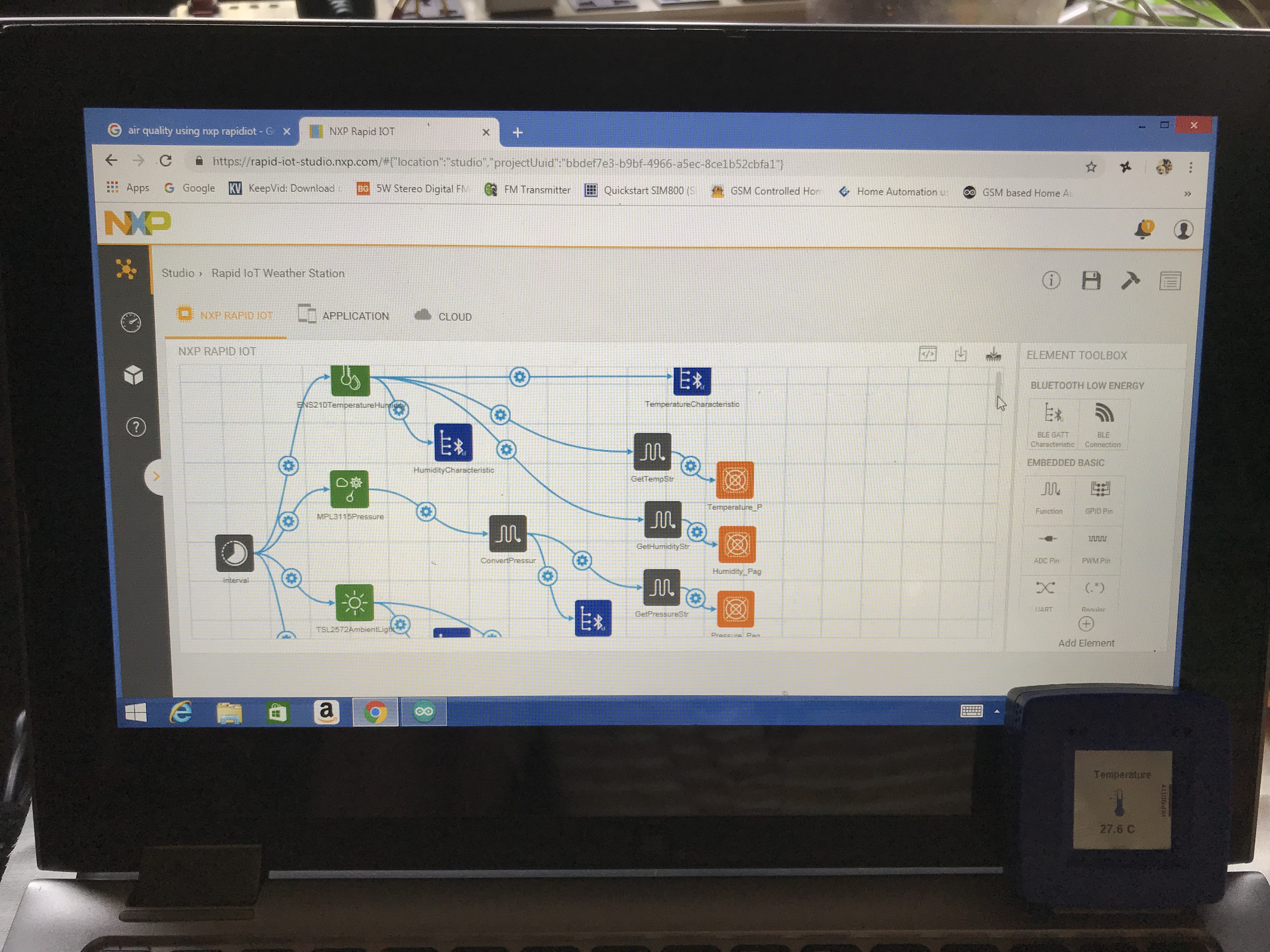
Navigate to Atmosphere Studio from the side menu. When you visit Studio for the first time in a session, you are brought to the Studio Projects screen.
- Click the
button. This displays a New Project window.
- Give the project a name. Then select the NXP Rapid IoT project type and click Create.
This opens a new project in Studio.
This guide walks through the step-by-step process to perform actions in Studio, but doesn't cover the in-depth aspects of Studio itself. To learn more about using Studio, its areas and features, and Studio elements, visit the Atmosphere Studiosection.Step 2 of 9: Create the Project’s Embedded Firmware
The first aspect of building this sample project is adding elements to Embedded View to create the project’s embedded firmware. This involves setting an interval to read embedded data, and to tell the interval to read the Rapid IoT’s ambient light sensor.
- Add the following elements to the canvas by double-clicking them in the Element Toolbox:
Interval element: The interval element sets the project to run at the time set in the element’s properties, which by default is set to once per second (1000 ms).
TSL2572 element: The TSL2572 element reads the hardware’s ambient light sensor data.
BLE characteristic element: The BLE characteristic element creates a GATT characteristic to use in your project. This element is a coupled element that bridges the project between Embedded View and Application View, meaning it’s included on both views.
- Connect the interval element to the TSL2572 element. This creates an event between them, which can be seen in either the interval element’s properties, or by clicking the connector’s
button. The event added is within the Interval trigger, with the TSL2572 ability Read Ambient Light. This means that when the interval element is triggered (which is every second), it will read the ambient light sensor’s value.
- Connect the TSL2572 element to the BLE characteristic element, which ties the value of the ambient light sensor to Application View. This creates an event between the two elements in the
Ambient Light Readtrigger ofSet Value, which sets a value for the project’s interface after it reads the raw sensor value. - Select the BLE Characteristic element on the canvas, which displays its properties in the properties panel. Set its Read Data Typeproperty to
Unsigned Integer, so the value it reads is an unsigned integer sent from the TSL2572 element. The element’s other properties may keep their default settings.
That’s all for work in Embedded View. To this point, an interval has been set to run once per second after the project opens, and when run will read the ambient light sensor.
Step 3 of 9: Create the Project’s InterfaceThe second aspect of building this sample project is adding elements to Application View to create the project’s visual component.
Click Application View to move to the application area of the project. Notice how the Element Toolbox has changed, and that the coupled BLE characteristic element is displayed on the canvas.
- Click the
button in Application View’s toolbar to display the interface builder. This area creates the visual interface for your project. By default this uses the smallest display size supported for an interface (320x560), but you can add an interface size by clicking the
button. Use the display size that fits best with your mobile device.
- Add an
interval element to the canvas, and connect it to the existing BLE characteristic element. This creates the trigger event Read, which reads the value of the BLE characteristic element sent from Embedded View every time the interval triggers.
- Add an
analog meter element to the canvas. The analog meter element displays a meter on a project’s interface to measure a value reading. Notice when the analog meter element is added to the canvas, a corresponding interface component is added to the interface builder. Click the analog meter component and move it to the center of the interface. Then in the element’s properties, change its Maximum Value to 10000.
- Connect the BLE characteristic element to the analog meter element. This creates an event between the two elements under the
Readtrigger forSet Value, which sets the value to the value of the meter when the BLE characteristic is read. Then in the event’s Valuefield, enterRead Data. This correlates the data read from the BLE characteristic element in Embedded View to set the analog meter’s value on the interface. - Add a
label element to the canvas. The label element displays text on a project’s interface. Click and move the label component on the interface centered above the analog meter component, then change the label’s text in its properties to read “Light Sensor Value.”
This is all that needs to be done for the project’s interface. To this point, an interval has been set that will read the BLE characteristic value once per second, which will display the light sensor value on the analog meter.
Step 4 of 9: Enable the Project’s Cloud ConnectivityThe last aspect of building this sample project is to enable it for cloud connectivity. This is done both on Application View and Cloud View
- While still in Application View, add a
cloud event element to the canvas. The cloud event element is a coupled element between Application View and Cloud View that enables a project’s data to be sent to Atmosphere.
- Connect the BLE characteristic element to the cloud event element. This adds the event
Sendto theReadtrigger, which sends the set value data to Atmosphere when the BLE characteristic is read. - Click Cloud View to move to the cloud area of the project. Notice how the Element Toolbox has changed, and that the coupled cloud event element is displayed on the canvas.
- Add a
cloud storage element to the canvas, and connect the cloud evemt element to the cloud storage element. This allows Atmosphere to store data sent to it from the connected cloud event element.
That’s all for creating the project! With the added cloud connectivity, the project will send the light sensor value from Embedded View to Application View (where it’s displayed on the mobile app’s interface), which then uses a cloud event to send it to Cloud View, where it’s connected to a cloud storage element to store the data on Atmosphere.
Step 5 of 9: Compile the ProjectOnce the project is finished, it needs to be compiled. Compiling readies the entire project’s source code for deployment.
From any view, click the
button in the project options menu on the top-right of the screen. You’ll see a loading graphic on the screen, and will receive a notification when the project is compiled.
Step 6 of 9: Program Firmware into the Rapid IoTWith the project compiled, your Rapid IoT can be programmed with the project’s embedded firmware.
Prior to programming a Rapid IoT, ensure you have the following setup configuration:
- The device is connected to the computer via USB.
- The project to be programmed has been compiled.
- The Rapid IoT is in programming mode.
To put the Rapid IoT into programming mode, perform the following steps:
- Connect the Rapid IoT to the computer via USB.
- Simultaneously hold the top-left and bottom-right side buttons for five seconds until the screen goes black. Continue holding the buttons while the screen goes black.
- The green LED will turn on and start blinking, indicating the device is now in programming mode. The side buttons can be released. While in programming mode, the Rapid IoT displays as a mass storage USB device on your computer.
With setup complete, you can program your Rapid IoT:
- While Embedded View is active, click the
button from the view’s toolbar. This downloads a .bin file containing the project’s compiled firmware.
- Locate the downloaded file on your computer, and move it into the Rapid IoT mass storage device. This initiates programming of the Rapid IoT, which is represented by a series of blinking lights on the device.
When the lights stop blinking, programming is complete and the Rapid IoT is programmed with the project’s embedded firmware. The Rapid IoT will reboot itself and no longer display as a mass storage device, and upon startup the project is loaded on the device.
Step 7 of 9: Register the DeviceWith firmware installed, the Rapid IoT can now be recognized and connected to Atmosphere. From here, open the Atmosphere IoT app on your mobile device. You’ll use the mobile app to both register the device and eventually view the label data on the project’s interface.
To register a device:
- Navigate to the Devices page, and click the
button in the top-right to display the Register Devices window. When the window opens it will automatically begin scanning for available devices within range.
- Ensure your Rapid IoT is within range from the device you are attempting to register from, otherwise it may not appear.
- The list of available devices appears. Select the Rapid IoT you just programmed and click Register.
The device is registered to Atmosphere and displayed on your Devices page.
Step 8 of 9: View the Project InterfaceEach registered device has its own dedicated dashboard, which displays its information and is where you access the device’s interface to interact with it. Select your newly-registered device on the Devices page to access its dashboard.
The interface created in Studio’s Application View is available on a device’s dashboard to interact with it. As long as the device is powered on and connected to Atmosphere, it can be interacted with.
To display the interface you created, click the
button at the top of the screen. This opens the project interface from within the Atmosphere IoT app.
The project’s interface displays the light sensor’s value on the analog meter, which updates once per second.
Step 9 of 9: View Device DataNow that the data is sent to Atmosphere, it can be viewed through one of the many device dashboard widgets available. In this guide an data meter widget can be used to display the light sensor’s value on the Dashboard similar to how it’s presented on the mobile app’s interface.
- To add a widget to the device’s dashboard, click the
button on the side of the page. This displays the menu of available widgets. Select the
data meter widget to add a meter to the dashboard.
- Once on the dashboard, click the widget’s
icon to display its settings. Then modify the following properties:
- Name: Give the widget a name, such as “Rapid IoT Light Sensor”
- Minimum Value: Set the minimum value to
0. - Maximum Value: Set the maximum value to
10000.
When the widget’s properties are modified, click Save.
NOW COMING TO ARDUINO PART
Step1:open arduino ide and select board and conifigure
Step2:now connect the nodemcu via cable to laptop
Step3:configure the correct com port
Step4:After thet click on the upload button
NOTE:*DONT FORGET TO CHANGE THE AUTH CODE AND WIFI CREDENTIALS*
NOW APP BUILDING
STEP1:download the blynk app from playstore and click on the add new project
STEP2:now add button widgets by clicking + symbol
STEP3:configure the widgets with the appliances
FINISHED EVERYTHING.
HERE IS THE FINAL VIDEO


Comments