


Hardware components | ||||||
 |
| × | 1 | |||
Software apps and online services | ||||||
| ||||||
 |
| |||||
 |
| |||||
Hand tools and fabrication machines | ||||||
 |
| |||||
Edge Impulse public project: https://studio.edgeimpulse.com/public/953867/live
GitHub repository: https://github.com/SamuelAlexander/face-following-robot-uno-q
Demonstration video: https://youtu.be/TYtrBvlE7Mc
IntroductionThis project combines computer vision and robotics on a single board. A camera captures video, a lightweight face-detection model (powered by Edge Impulse) locates the face, and a proportional controller converts that position into differential wheel commands, all at ~10-15 FPS.
The UNO Q's split architecture makes this possible:
- MPU (Qualcomm, Linux) --> runs the ML model and control logic in Python
- MCU (STM32, Zephyr RTOS) --> drives servo PWM with real-time precision
The two processors communicate over Bridge RPC, a MessagePack-based protocol over an internal serial link. This separation keeps heavy inference off the real-time path and motor control deterministic.
A browser-based Web UI lets you monitor detections and tune steering parameters live, no recompilation needed.
What you'll learn
- How the UNO Q's MPU/MCU split architecture works
- Using App Lab bricks (pre-built middleware) for AI and web interfaces
- Bridge RPC communication between Python and an Arduino sketch
- Proportional steering control for differential-drive robots
- Live parameter tuning through a Socket.IO web dashboard
Hardware
Software
- Arduino App Lab v0.6 or later (runs in-browser, no local install needed)
- A computer on the same network as the UNO Q
- Edge Impulse Studio account
Source code
The full project source is available at: https://github.com/SamuelAlexander/face-following-robot-uno-q
Architecture overviewThe system has three layers:
Why split MPU and MCU? ML inference is computationally heavy and non-deterministic, it belongs on a Linux processor. Servo PWM timing is safety-critical and must be jitter-free, it belongs on a real-time microcontroller. Bridge RPC connects the two with ~8 ms round-trip latency.
Hardware assemblyChassis overview
The robot uses a simple differential-drive layout:
- Two continuous-rotation servos mounted on opposite sides
- A rear caster or skid point for stability
- A top-mounted platform for the UNO Q and camera
- The USB power bank sits on or below the platform as ballast
Continuous-rotation servos simplify wiring. A 1500 us pulse means stop, below 1500 spins one way, above 1500 spins the other.
Wiring
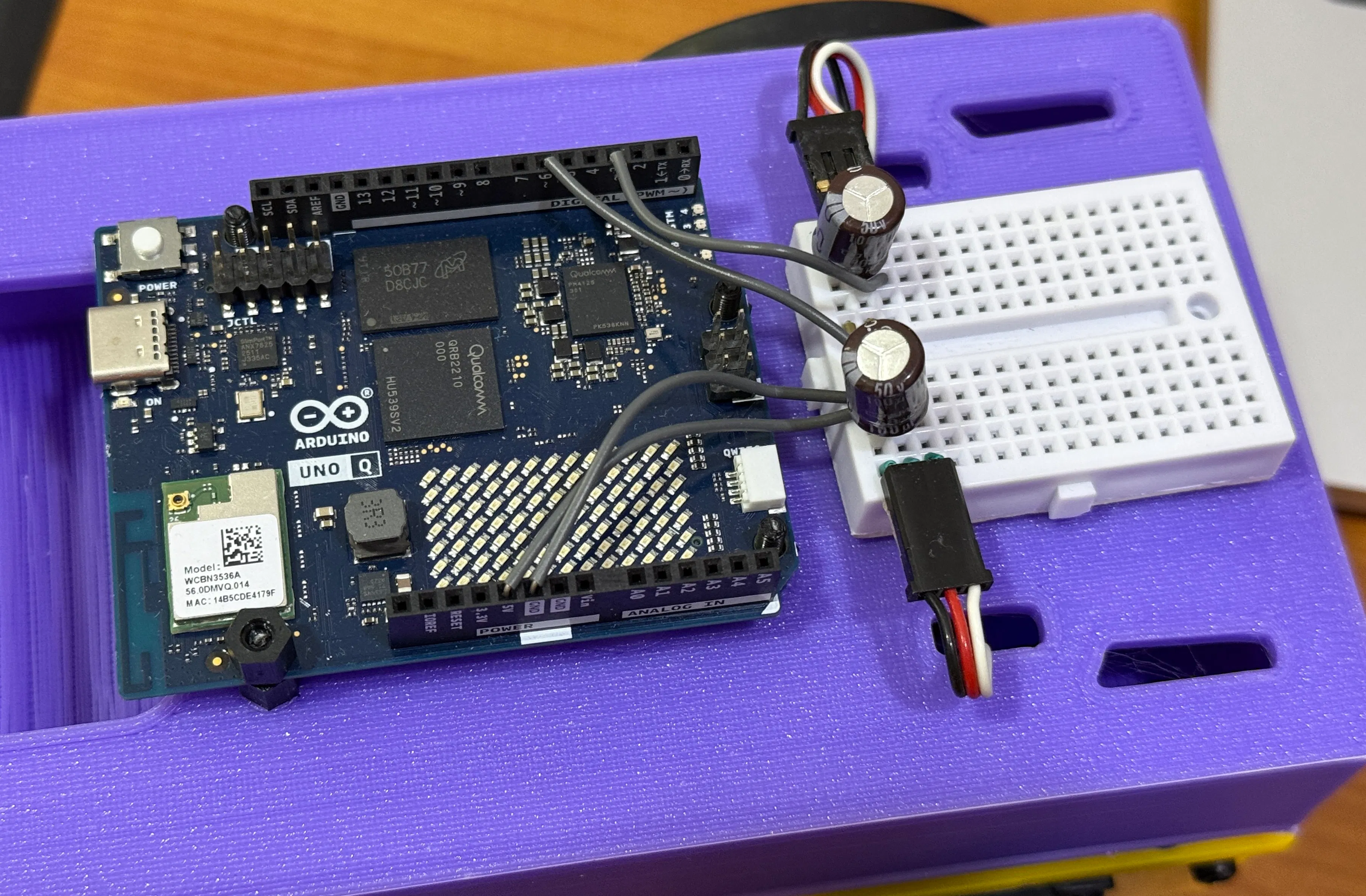
Place a 100 uF capacitor across the servo power and ground rails to absorb current spikes.
Connect the webcam to the USB-A port on the USB-C splitter. The USB-C side powers the UNO Q.
> Note: The right servo is mounted mirrored relative to the left. The firmware handles this with a pulse inversion flag, no crossed wires needed.
Project setup in App LabFile structure
Every App Lab project follows this layout:
Configuring bricks
Bricks are pre-built middleware packages that run on the MPU. They provide high-level capabilities without writing boilerplate. This project uses two:
In app.yaml:
```yaml
name: Detect and follow robocar
description: Robot car that follows a target object.
bricks:
- arduino:video_object_detection:
model: face-detection
- arduino:web_ui: {}
icon: 🚙
```
- video_object_detection, captures camera frames, runs the face-detection model, and delivers results to your Python code via callbacks
- web_ui, serves the HTML/JS dashboard and provides a Socket.IO server for real-time communication
The model: face-detection line selects a built-in lightweight face-detection model. No training or Edge Impulse account needed.
Sketch dependencies
In sketch/sketch.yaml, the key libraries are Arduino_RouterBridge (Bridge RPC) and Servo (PWM output):
```yaml
profiles:
default:
fqbn: arduino:zephyr:unoq
platforms:
- platform: arduino:zephyr
libraries:
- Arduino_RouterBridge (0.4.1)
- Servo
- MsgPack (0.4.2)
```
The MCU sketch: Servo controlThe MCU firmware is intentionally minimal, it receives pulse-width commands over Bridge RPC and writes them to the PWM hardware. All decision-making lives on the MPU.
Bridge RPC endpoint
The sketch exposes a single function that the MPU can call. It uses the Arduino Servo library for reliable pin-level PWM output:
```cpp
#include <Arduino_RouterBridge.h>
#include <Servo.h>
Servo leftServo;
Servo rightServo;
bool set_wheel_pwm(int left_us, int right_us) {
uint32_t left = clamp_pulse_us(left_us); // Clamp to 1000-2000
uint32_t right = clamp_pulse_us(right_us);
left = apply_invert(left, kInvertLeftWheel); // false
right = apply_invert(right, kInvertRightWheel); // true — right is mirrored
leftServo.writeMicroseconds(left); // D3
rightServo.writeMicroseconds(right); // D6
return true;
}
void setup() {
Bridge.begin();
leftServo.attach(3);
rightServo.attach(6);
leftServo.writeMicroseconds(1500); // Start stopped
rightServo.writeMicroseconds(1500);
Bridge.provide_safe("set_wheel_pwm", set_wheel_pwm);
}
void loop() {} // All control is event-driven via RPC
```
Key concepts:
- Arduino Servo library handles PWM output via attach(pin) and writeMicroseconds(). This is more portable than the low-level Zephyr PWM API (pwm_set_dt), which depends on devicetree index mappings that can vary between board revisions.
- Bridge.provide_safe() registers the function so it runs in the Arduino loop() context, safe for hardware operations like PWM writes. Never use Bridge.provide() for GPIO/servo/motor calls, as that runs in a background RPC thread where hardware APIs can fail.
- Pulse inversion handles the mirrored right servo: inverted = 3000 - pulse. This mirrors the pulse around the 1500 us stop point, so the same "forward" command from Python moves both wheels in the same physical direction.
- Empty loop() is correct, the Bridge library hooks into the loop internally to dispatch queued provide_safe callbacks.
Continuous-rotation servo basics
| Pulse (us) | Behavior |
| ---------- | ------------------------------ |
| 1500 | Stop |
| 1000 | Full speed, one direction |
| 2000 | Full speed, opposite direction |
The closer to 1500, the slower the wheel turns. This project uses offsets up to ±125 us for responsive but desk-safe motion.
The MPU application: Detection to steeringThe Python application on the MPU handles three responsibilities: receiving detections from the vision brick, computing steering commands, and communicating with both the MCU and the web UI.
Brick initialization
```python
from arduino.app_utils import App, Bridge
from arduino.app_bricks.web_ui import WebUI
from arduino.app_bricks.video_objectdetection import VideoObjectDetection
ui = WebUI()
detection_stream = VideoObjectDetection(confidence=0.5, debounce_sec=0.0)
```
The VideoObjectDetection brick fires a callback every time it processes a frame. The on_detect_all variant fires for every frame, including ones with no detections, useful for keeping a watchdog timestamp fresh:
```python
detection_stream.on_detect_all(on_detections)
App.run()
```
Detection format
The brick delivers detections as a dictionary, with each label mapped to a list of detection instances:
```python
{
"face": [
{"confidence": 0.89, "bounding_box_xyxy": (144, 83, 234, 209)},
#...more faces if multiple detected
]
}
```
Each instance contains a confidence score and a bounding_box_xyxy tuple of (x_min, y_min, x_max, y_max) in pixel coordinates. The TARGET_CLASS constant must match the model's label exactly, "face"` for the built-in face-detection model.
> Important: The per-label value is always a list, even for a single detection. Code that expects a plain dict per label (without the list wrapper) will silently miss all detections.
Proportional steering controller
The controller converts the face's horizontal position into differential wheel commands:
```
1. Find the face's bounding box center
2. Normalize to 0.0 (left edge) — 1.0 (right edge)
3. Compute heading error: (center - 0.5) x 2.0 → range -1.0 to +1.0
4. Apply deadband (ignore small errors to suppress jitter)
5. Shape response with a power curve (compress large errors)
6. Scale by STEER_GAIN → turn speed
7. Convert to differential pulses: left = 1500 + turn, right = 1500 - turn
```
```python
heading_error = (target_cx - 0.5) * 2.0
if abs(heading_error) < CENTER_DEADBAND:
heading_error = 0.0
shaped = math.copysign(abs(heading_error) STEER_CURVE, heading_error)
turn = clamp(STEER_SIGN * STEER_GAIN * shaped, -MAX_TURN_SPEED, MAX_TURN_SPEED)
left_us = speed_to_pulse(turn) # 1500 + turn x 500
right_us = speed_to_pulse(-turn) # 1500 - turn x 500
```
The power curve (STEER_CURVE = 0.4) makes the response more aggressive for small errors and softer near the frame edges, a simple alternative to PID that works well for this use case.
Coasting and lost target
When the face momentarily disappears (occlusion, blink, brief look-away), the controller coasts on the last-known position for TRACKING_TIMEOUT seconds (default 0.5s) before declaring the target lost. This avoids jittery stop-start behavior.
When the target is truly lost, the robot stops. An optional search mode (disabled by default) slowly rotates to scan for the face.
Bridge communication and rate limiting
The UNO Q Bridge has no internal queue, sending commands too fast crashes the serial link. The application rate-limits Bridge calls to a maximum of 20 Hz (50 ms intervals):
```python
MIN_BRIDGE_INTERVAL = 0.05 # seconds
if now - _last_bridge_ts < MIN_BRIDGE_INTERVAL:
return # Skip this update
Bridge.notify("set_wheel_pwm", left_us, right_us)
```
Bridge.notify() is fire-and-forget (no response waited), which avoids blocking the inference loop. Bridge.call() would wait for a return value and slow down the control loop.
> Safety note: The emergency stop bypasses rate limiting entirely to guarantee the MCU receives the stop command immediately.
Watchdog
A background thread checks whether detection callbacks have stopped arriving. If no callback fires for 1.5 seconds (indicating a camera or pipeline failure), the watchdog forces a stop command:
```python
def _watchdog_loop():
while True:
time.sleep(0.25)
if time.monotonic() - _last_detection_ts > NO_DETECTION_TIMEOUT:
send_lost_target_command()
```
The web UIThe dashboard runs in any browser on the same network and provides live monitoring and parameter tuning.
Features
All slider changes take effect immediately via Socket.IO, no restart required. This makes tuning fast: adjust a slider, observe the robot's response, repeat.
Deploy and runApp Lab GUI
1. Open Arduino App Lab in your browser
2. Create a new app or import the project files
3. Click Run, App Lab compiles the sketch, flashes the MCU, and starts the Python app
First boot checklist
1. Check the log for the sample_detections line, it prints the raw detection payload on the first frame. Verify:
- The label is "face" (matches TARGET_CLASS)
- The bounding box coordinates are reasonable for your camera resolution
2. Open the Web UI at http://<UNO_Q_IP>:7000, you should see the video stream and detection events appearing in "Recent detections"
3. Verify servos, press the Motor Test button in the UI. Both wheels should turn left, pause, then turn right. If not, check wiring and servo power before proceeding to face tracking.
Tuning guideSteering direction
If the robot turns away from your face instead of toward it, flip the steering sign in main.py:
```python
STEER_SIGN = -1.0 # Flip if left/right tracking is mirrored
```
Frame width calibration
Check the sample_detections log output. If the max x coordinate in bounding_box_xyxy is significantly different from FRAME_WIDTH_FALLBACK (default 640), update the constant to match. A wrong value causes asymmetric or weak steering.
Gain tuning
Start with these defaults and use the Web UI sliders to adjust:
Workflow: Start with the robot on a desk. Increase STEER_GAIN until the robot centers on your face smoothly. If it oscillates (overshoots left-right), reduce the gain. Once tuned, update the defaults in main.py so the robot starts with good values.
Troubleshooting


_t9PF3orMPd.png?auto=compress%2Cformat&w=40&h=40&fit=fillmax&bg=fff&dpr=2)


Comments