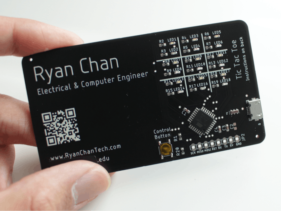
With the internship application season in full swing, I decided to make some PCB business cards that I can give away to hopefully stand out from the crowd. This card specifically plays the classic game of tic tac toe.
Like normal Tic-Tac-Toe, there is a grid with 9 positions that a player can place their mark. One player is Blue and the other player is Red instead of the traditional X and O. Your current position is marked by a blinking blue or red LED. Pressing the button quickly will move you to a new position. Once you are at the desired position, you press and hold the button to place their mark and the turn moves to the other player. The first player to get three marks in a row wins.
The card is set to 2-player mode, but there is also a single-player mode that the user can activate by pressing and holding the main button for more than 5 seconds. The display will show a "1" to indicate single-player mode. To switch back to 2-player mode, the user just has to press the main button again for 5 seconds. The display will then show a "2" to indicate 2-player mode.
VideoPart 2:
Here is a video of the most recent version of the card with the fixes from Part 1:
Part 1:
The DesignThe display is made up of 18 LEDs organized into 9 segments where there is a blue and red LED in each segment. There is a single button that the player uses to control where they will place their mark. There is also a micro-USB port that is used to power the card.
An ATmega328P-AU in a TQFP package is used as the brains to control everything. It is bootloaded with the Arduino Uno bootloader since I found that to be the most convenient and low-cost way to program it (although there are other ways to do it).
I have attached the Schematics and Code in case you are curious about how it works and would like to make your own. It includes the fixes discussed in the video. However, I did not include the Board Design because I believe business cards should be unique and reflect your own style.
InstructionsHardware Instructions:
1.) Build or download the schematic found in the Schematic section at the bottom of the page in your preferred EDA program (I used Autodesk EAGLE).
2.) Route the board. Have fun designing it and make it unique!
3.) Export the Gerber file and send it to a PCB manufacturer (preferably one that offers SMD assembly) to get it produced (I used JLCPCB).
Software Instructions:
I used an Arduino Uno to program my card, but there are other methods that may be easier. To use the same method I used, follow these steps (here is a more in-depth tutorial from Arduino):
4.) Wire the card for Bootloading. To do this, connect pins 10, 11, 12, and 13 on the Arduino Uno to pins RST, PB3, PB4, and PB5 on the card respectively. Also connect the Arduino's 5V and GND to the card's 5V and GND.
5.) Upload the Arduino ISP to the Arduino Uno and burn the Bootloader. To do this, open the Arduino IDE, and open File > Examples > ArduinoISP > ArduinoISP. This will open a sketch. Upload this to your Arduino Uno. Next, burn the Bootloader by going to Tools > Burn Bootloader.
6.) Wire the card for Programming. To do this, first remove the ATMega328P chip from the Arduino Uno using a screwdriver (remember to put the chip back when you're done!). Next, connect the Arduino's RX to the card's TX and the Arduino's TX to the card's RX. Also connect the Arduino's 5V and GND to the card's 5V and GND.
7.) Upload the Tic-Tac-Toe code to the card. To do this, download the code from the Code section and press the upload button in the Arduino IDE.


_t9PF3orMPd.png?auto=compress%2Cformat&w=40&h=40&fit=fillmax&bg=fff&dpr=2)


Comments