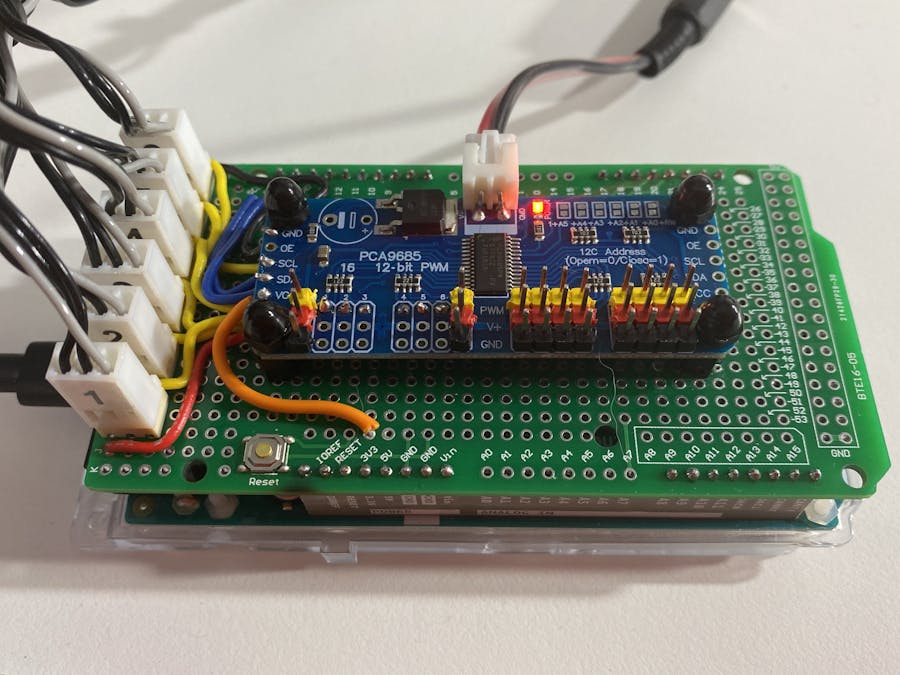
My first robot arm was an Arduino TinkerKit Braccio. As I learned more about robot arms I developed aspirations to use reverse kinematics libraries and connect to the Robot Operating System (ROS) amongst other things. These goals become easier on a microcontroller with a larger processor and more memory than the Uno which the shield supplied which the Braccio is designed for. I chose Arduino Due as the the next iteration of microcontroller.
Now I had to figure out a way to make a backwards compatible alternative to the Braccio shield, to be suitable for the Arduino Due.
DesignStill being relatively new to electronics, my preference was to use an off-the-shelf module to provide a secondary higher current power supply for the servos. I knew that I'd have to carefully protect the 3.3V Arduino Due from the higher voltages and currents (5V 4A) of the Braccio servos, and I was a bit worried about designing it myself.
I selected an I2C based Adafruit module. I found through research and testing that the module was 3.3V compatible on the logic side, while still able to deliver the Braccio standard 5V 4A power on the servo side. One interesting side effect of this approach is that the PWM signal output to each servo has a Vpp (voltage peak to peak) of 3.5V which the servos still recognise as a high TTL logic level.
The Arduino Due sized prototyping shield is intended as a simple mounting mechanism for the Adafruit module and the connectors for Servo leads. The only Arduino Due pins required are the I2C wire interface and power for the logic circuits. Wire1 was selected simply to keep the connection neat and minimal (Arduino Due has two I2C/wire interfaces).
- D71 (SCL1) connects to PCA9685 SCL
- D70 (SDA1) to SDA
- 3V3 to Vcc
- GND to GND
Finding the specific three wire connectors used on the original Arduino Uno Braccio shield was the key to maintaining physical compatability. These were identified as Molex KK-254 (also known as KF2510) connectors. It‘s importnant to note that the wiring of the Braccio connections is unconventional compared to most other hobbyist servos. You can't just modify the Braccio servo connectors and plug them directly to the PCA9685 module as the pins are in different arrangements.
The PCA9685 is usually supplied with screw gate power terminals for connecting an external power supply. I chose to swap this for a right angle mount JST XH connector. I confess this is a bit of a cludge, as the pin alignments don't exactly match up and the legs on the JST connector have to be splayed a little. If the connector is not a right angle type, then this mistreatment will misalign the pins. I then handmade a short power adapter lead (see photograph) to enable the original Braccio wall plug power supply to still be used to power the servos.
The signal connections are soldered to Pins 1 through 6 on the PCA9685 to align the pin numbers with the Braccio servo numbering scheme.
You may notice in the photograph below that only relatively few header pins are connected to make the shield easy to install and deinstall. Because of the height of the shield I did not use stackable headers, but in hindsight this would be useful for accessing other arduino pins later (e.g., if you were adding other sensors).
The V+ and GND connections to the Molex KK connectors are soldered as tracks. with each PWM signal soldered to each connector’s middle pin.
In the underside photo you might notice some unexplained extra soldered connections in the top left corner of the picture. This is an LED motor power indicator and accompanying resistor which I added later. See closeup below.
As I was soldering the wiring directly into pins 1 through 6 on the PCA9685, I did not solder in pin header on those ports. In hindsight, pin header would have been useful for attaching test equipment (e.g., multimeter and oscilloscope).
When I moved on to building another robot arm, I reused this design approach. The new arm used conventional hobbyist servo connections which could connect directly to the PCA9685 pin headers, removing the need for the Molex-KK connectors. The extra space made available on the prototyping shield was useful for breaking out sensor connectors and other stuff.


Comments