


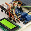
Hardware components | ||||||
 |
| × | 1 | |||
Software apps and online services | ||||||
| ||||||
In this Visual Programming Visuino tutorial, we’ll use the Arduino Uno R4 WiFi’s built-in LED Matrix and WiFi connection to display the current temperature from any city using the free wttr.in weather service.
The Arduino connects to the internet and requests the latest weather data from wttr.in. The current temperature is then extracted from the response and displayed directly on the onboard LED Matrix, creating a compact real-time weather display without any external hardware.
To keep the information current, the temperature is refreshed automatically every 5 minutes. You can easily customize the refresh interval and select any city supported by wttr.in.
Using Visuino’s drag-and-drop interface, you can configure the WiFi connection, download weather data from wttr.in, extract the temperature value, and display it on the LED Matrix without writing any code.
This project is an example of what you can build — wttr.in offers many more weather parameters such as humidity, wind speed, pressure, forecasts, and detailed multi-day data. This means you can easily expand this project into a full weather station directly on the Arduino Uno R4 WiFi.
Combined with other Visuino tutorials, you can add extra sensors, additional API data, or multiple display modes to create a more advanced and interactive system. The possibilities are wide open, making this just a starting point for much bigger weather or IoT dashboard projects.
Note: No external sensors or displays are required — everything runs on the Arduino Uno R4 WiFi using its built-in WiFi and LED Matrix.
Watch the Video!
Step 1: What You Will Need- Arduino UNO R4 Wifi
- Visuino program: Download Visuino
Start Visuino as shown in the first picture Click on the "Tools" button on the Arduino component (Picture 1) in Visuino When the dialog appears, select "Arduino UNO R4 WiFi" as shown on Picture 2
Step 3: In Visuino Set WiFiSelect Arduino UNO R4 WiFi board and in the editor Modules>WiFi>Access Points, click on [...] button, so that "Access points " window will open.In this editor drag the WiFi access point to the left side.
- In the properties window Under "SSID" put the name of your WiFi Network
- Under "Password" put the access password for your WiFi network
- Close the "Access points" window
- On the left in editor select Modules>Wifi>Sockets, click on [...] button, so that "Sockets" window will open Drag the TCP/IP Client from right to the left side, then Under Properties window set port: 80 and host: wttr.in
- Close the "Sockets" window
- Add "Char To Text" component
- Delete Right Sub Text" component
- Add "2x Delay" component
- Add "Start" component
- Add "HTTP Client" component
- Select ArduinoUNO R4 WiFi board and in the properties window expand Modules>Display and select Elements and click on the 3 dots button, in the Elements window drag "Text Field" to the left side and in the properties window select "Elements" and click on the 3 dots.
- A new Elements window will open, Drag the "Font" element to the left and in the properties set the font "Adafruit\Picopixel"
- Close the "elements" windows
- Select "CharToText1" and in the properties window set "Max Length" to 300
- Select "Delay1" and in the properties window set "Interval" to 2000000
- Select "HTTPClient1" and in the properties window et "Host" to wttr.in
- Double click on the "HTTPClient1" and in the Requests window drag "Get" to the left side and in the properties window set "URL" to /London?format=%t
Note: in this example we are requesting data for London but you can change the city in the url to any other location: /Miami?format=%t
- Select "Delay2" and in the properties window set "Interval" to 300000000 this is the refresh time for the data (Temperature) in micro seconds, you can change this value according to your needs.
- Select "DeleteRightText1" and set "Length" to 3
- Connect Arduino Sockets pin [Out] to "Delay1" pin [Start]
- Connect "Delay1" pin [Out] to "Arduino Sockets pin [Disconnect]
- Connect "Delay1" pin [Out] to "CharToText1" pin [Clock]
- Connect "HTTPClient1.Requests.GET1.Response" pin [Content] to "CharToText1" pin [In]
- Connect "CharToText1" pin [Out] to "DeleteRightText1" pin [In]
- Connect "DeleteRightText1" pin [Out] to "Arduino.Modules.Display.Elements.Text Field1" pin [In]
- Connect "HTTPClient1" pin [Out] to "Arduino.Modules.Communication.WiFi.Sockets.TCP Client1 [wttr.in:80]" pin [In]
- Connect "Start1" pin [Out] to "HTTPClient1.Requests.GET1" pin [Clock]
- Connect "Delay2" pin [Out] to "Delay2" pin [Start]
- Connect "Start1" pin [Out] to "Delay2" pin [Start]
In Visuino, at the bottom click on the "Build" Tab, make sure the correct port is selected, then click on the "Compile/Build and Upload" button.
Step 8: PlayCongratulations! You have completed your project with Visuino. Also attached is the Visuino project, that I created for this tutorial, you can download it and open it in Visuino: https://www.visuino.com


Comments