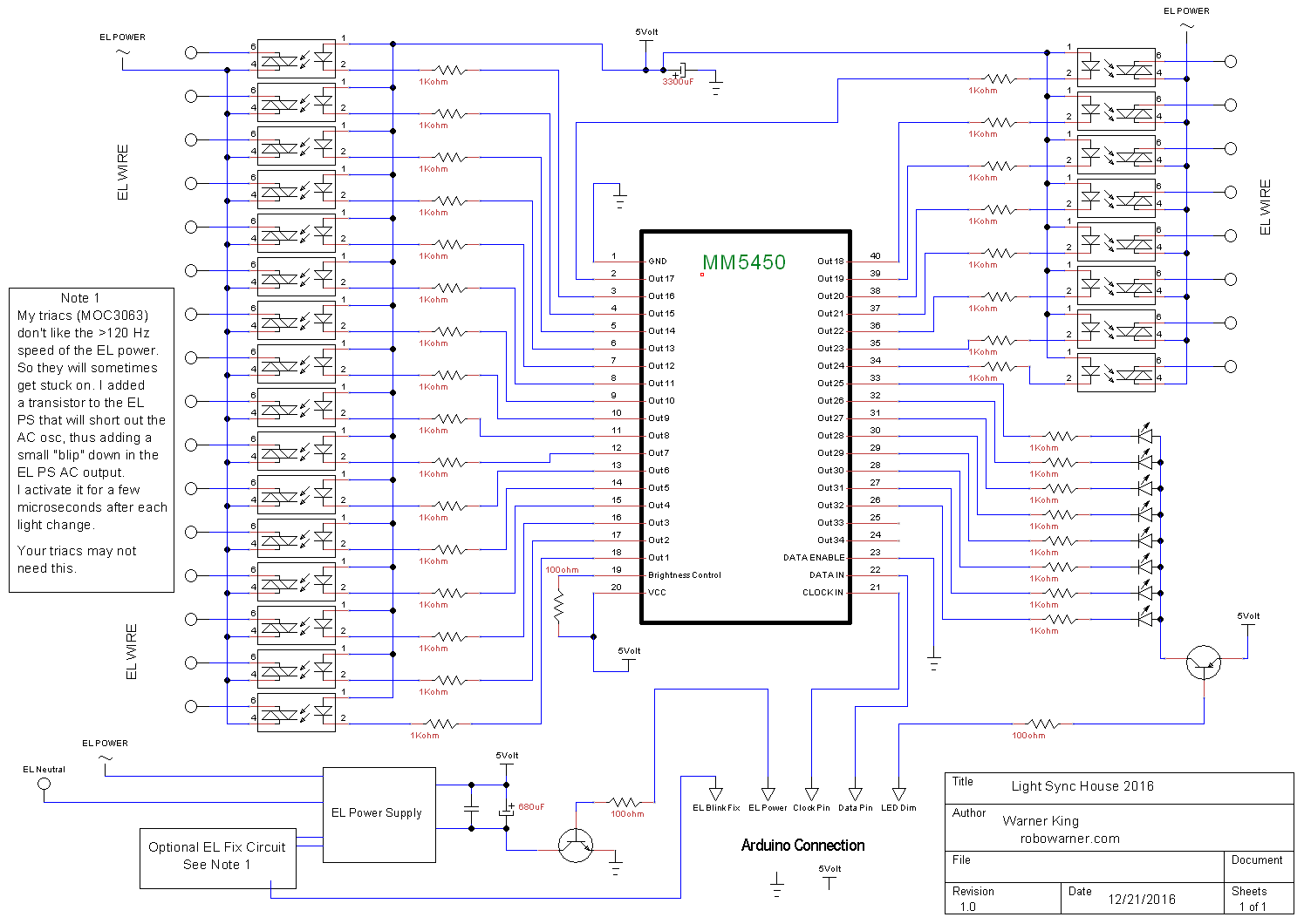
//Light House Control 2016
//Warner King
//RoboWarner.com

//MM5450 code from l.e. hughes
// Date.....: 27 May 2011
// His Notes....: Basic, simple example of using shift registers to control the MM5450/5451
//            LED driver. This program was specifically written for the 5450, but should
//            also work with the 5451 and be easily modified for others. The 5450/5451
//            is latching and requires 36 signal databits to send all of the information
//            to control the LEDs (34 for the 5450; 35 for the 5451). There are minor
//            differences in the chip between the manufacturers, please read the appropriate
//            datasheet(s) before connecting power.
//

#define BITSB 8                        // number of bits per byte, used for code clarity
#define DATABITS 36                    // what we must send to the chip in order to control the lights
#define STARTBIT 1                     // value of the starting bit;

const int ledDim = 5;   //LED common pin, used with PWM for a dimming effect
const int ELpower = 3;  //EL power supply power, also used with PWM for dimming
const int ELblink = 2;  //Used to fix EL wires getting stuck on, is pulsed after each refresh to reset stuck triacs.
const int clockPin  = 4;               // connect Arduino pin 3 to clock pin (21) on the 5450
const int dataPin   = 6;               // connect Arduino pin 6 to data pin (22) on the 5450

const int numOfLightChannels = 32;
const int numDimChannels = 2;
const int startBytes = 2;

// The following line just computes the number of bytes we will need in the ledArray to hold all of
// bits of data for the signal; it could be declared statically.
//
const int arrayLen  = (int)((DATABITS-1)/BITSB) + 1;

// This is the actual array that will hold the signal bits. This program, for the 5450/5451, will
// need 5 bytes for a total of 40 bits.
//
byte ledArray[arrayLen];               // for this chip, length is 5 and that could hold 40 values

int myInts[40];   //Holds the data received from Vixen
int errorReset = 0;       //Used to reset the serial input code if bad data is gathered.
bool ELpowerflag = false;   //Used to automatically turn off EL power supply if not in use.


typedef enum {                         // this exists primarily for code clarity
 OFF, ON
} ledState;

void setup() {
   Serial.begin(115200);
  pinMode(LED_BUILTIN, OUTPUT);
  pinMode(clockPin, OUTPUT);           // we don't need a latch pin since the 5450/5451 latched after
  pinMode(dataPin,  OUTPUT);
  pinMode(ledDim,  OUTPUT);
  pinMode(ELpower,  OUTPUT);
  pinMode(ELblink,  OUTPUT);
  digitalWrite(ledDim, LOW);
  digitalWrite(ELpower, LOW);
  digitalWrite(ELblink, LOW);

 allOff();
 sendDatabits();
// allOn();
// sendDatabits();
 delay(1000);
 }

// the loop function runs over and over again forever
void loop() {

  if (Serial.available() >= (numOfLightChannels + startBytes + numDimChannels)) {
    for(int y = 0; y <= (numOfLightChannels + startBytes + numDimChannels); y++)
    {
      myInts[y]= Serial.read();    //Gather data and store it in the array
    }
    if (myInts[0] == 126)     //First two bytes transmitted each refresh by the Renard Plugin version 1
    {
        if (myInts[1] == 128)
        {
          errorReset = 0;       //Valid signal, reset error counter
          ELpowerflag = false;
          for (int p = 0; p <= (numOfLightChannels); p++)   //Translate data gathered from Vixen to the MM5450 array
          {
            if (myInts[p+1] == 255)     //255 is full intensity on in Vixen
            {
               setLight(p, ON);
               if(p <= (startBytes + 21))     //If any EL wire channels are on, let the EL power supply be activated
               {
                      ELpowerflag = true;
               }
            }
            else
            {
              setLight(p, OFF);
            }
          }
          int ledMap = map(myInts[34], 0, 255, 255, 50);    //Mapping for dimming.

          int elMap = map(myInts[35], 0, 255, 40, 255);
          if (ELpowerflag == false || myInts[35] == 0)    //If no EL wire is turned on, turn off EL power supply
          {
            elMap = 0;
          }
          delay(90);    //Timing to get lights in sync with Vixen, as the program outputs data before the actual point it's needed in the song.
          analogWrite(ledDim, ledMap);  //PWM for the dimming on the LEDs and EL power supply
          analogWrite(ELpower, elMap );
          sendDatabits();  //Send data out to MM5450
            if (myInts[20] == 255)  //Activates built in LED, used for timing.
            {
               digitalWrite(LED_BUILTIN, ON);
            }
            else
            {
                digitalWrite(LED_BUILTIN, OFF);
            }
          digitalWrite(ELblink, HIGH);   //Dirty fix for EL wire triacs getting stuck on, after each light refresh this will activate a transister to short out the EL AC output
          delayMicroseconds(250);        //thus allowing the stuck triacs to turn off. The delay is small enough it's not noticable to the eye.
          digitalWrite(ELblink, LOW);
        }
    }
  }
  //Used to reset the serial input code if bad input is sent.
  //Otherwise the above code will constantly loop and never find the proper data in the first 2 bytes.
  else if (Serial.available() > 1)
  {
    errorReset++;
    if (errorReset > 30)
    {
      while(Serial.available() > 0)
      {
        int trash = Serial.read();
      }
      errorReset = 0;

    }
  }
  delay(1); //Delay to prevent chaos
}


// Subroutine that sends all of the DATABITS to the chip. It begins by first sending the startbit, then it
// uses the Arduino shiftOut function to send the bits in each byte of the ledArray. I could have put the
// STARTBIT into the ledArray but decided that I liked it better outside of the array. Any time you want
// to turn lights on or off, this routine must be called after setting the appropriate bits in the ledArray.
//
void sendDatabits() {
 digitalWrite(clockPin, LOW);
 delay(2);
 digitalWrite(dataPin, STARTBIT);
 delay(2);
 digitalWrite(clockPin, HIGH);
 delay(5);
 digitalWrite(clockPin, LOW);
 delay(2);
 for(int i = 0; i < arrayLen; i++) {
   shiftOut(dataPin, clockPin, LSBFIRST, ledArray[i]);
 }

}

// Subroutine that takes a light (output pin) as a sole argument and sets the bit value for that pin
// to the opposite of its current setting (toggle).
//
void toggleLight(int pin) {
 byte arrayElem = int((pin-1)/BITSB);                     // which element of the ledArray is pin in
 byte byteElem  = (pin - (arrayElem * BITSB)) - 1;        // and which bit in that byte is the pin
 ledArray[arrayElem] ^= (1 << byteElem);                  // toggle byteElem
}


//This is modified from the original code, I added the bitWrite instead of using the original shift (<<) method.
//It sets the selected pin to ON or OFF
void setLight(int pin, byte val) {

 byte arrayElem = int((pin-1)/BITSB);                     // which element of the ledArray is pin in
 byte byteElem  = (pin - (arrayElem * BITSB)) - 1;        // and which bit in that byte is the pin
byte temp1 = ledArray[arrayElem];
 bitWrite(temp1,byteElem , val) ;
ledArray[arrayElem] = temp1;
}

// Subroutine that turns all lights on. Because the STARTBIT is 1 or ON, we don't want to set any
// bits above 35 to ON, lest it be interpreted as the start of another set of databits. Better error
// checking would be to make sure that no bit > 35 was ever set to 1.
//
void allOn() {
 for(int i = 1; i < DATABITS; i++) {
   setLight(i, ON);
 }
}

// Subroutine that turns all lights off
//
void allOff() {
 for(int i = 0; i < arrayLen; i++) {
   ledArray[i] = 0;
 }
}


_PnKPri8a6q.jpg?auto=compress%2Cformat&w=48&h=48&fit=fill&bg=ffffff)


Comments