


RoBug is a small quadruped robot that combines simplicity, affordability and advanced robotics features under one roof. RoBug was designed to be both, a beginner friendly project for everybody who wants to dive into robotics without spending a fortune for parts and tools, but also an open, modular and feature-rich platform for advanced robotics experiments. No matter if you want to navigate RoBug through your room with the RoBug Remote Control App running on your mobile phone or if you want to experiment with autonomous navigation or obstacle detection, this project is for you.
The main design goals were:
- a small, budget-friendly walking robot that can interact with us by expressing his "mood" visually and through "body language" - like a mechanical pet
- an open, feature-rich, yet affordable hardware platform that is simple enough to build for educational purposes but also versatile enough for in-depth robotics experiments.
- an open and modular software architecture including a high-level API that makes it easy to develop RoBug applications.
- a flexible motion controller with parametrized gait generator that enables nimble, organic looking dynamic gaits.
Adding wheels would be a lot easier, right? Correct - but also a lot more boring ;-) The main reasons why I'm more interested in legged than in wheeled robots are:
- walking is a fascinating way of locomotion. Walking robots, quadruped robots in particular, are a great opportunity to learn about the biomechanics behind walking and life on earth in general.
- legged robots are a little bit more mechanically complex, even though RoBug has only 8 degrees of freedom. They are the perfect learning vehicle for concepts like torque, stability, inverse kinematics and so on.
- it is incredibly satisfying to see a self-designed, self-built and self-programmed mechanical creature walking around in your room - believe me :-)
Cost and part availability were important aspects in the whole RoBug design process. The lower the overall cost and the better the part availability, the lower the hurdle to build a RoBug. Depending on where you are located, the required parts will total up to about 60€ to 70€ plus 3d-printed parts. No special parts were used, Check out the parts list in the download section, I added links to suppliers for your convenience.
Feature Summary- special 2DOF leg topology for wide range of motion, 8 DOF total
- low body weight and speedy servos enable dynamic gaits
- compliant foot tips to absorb shock and conserve energy when walking
- pwm-controlled LED "eyes" can express RoBugs mood
- touch sensors on RoBugs back and belly enable hand contact detection
- ToF distance sensor for obstacle detection and avoidance
- Raspberry Pico 2 WH with more than enough compute power and I/O
- wifi and bluetooth thanks to the Raspberry Pico 2 WH
- open-hardware RoBug Base Board for easy assembly
- open-source software stack written in MicroPython
- RoBug Quick Start Application templates
- URDF and Webots PROTO simulation models
I'm a passionate Blender user for over two decades and I'm using it for all my constructions. Blender is such a flexible software package and there are many plug-ins around for 3d-printing, mechanical design and export into lots of formats. I guess CAD people will strongly disagree but in my humble opinion, Blender is close to ideal for DIY robotics. And because RoBug radically follows the open-hardware/open-source approach, the complete blender design file is available for download on the bottom of the page.
The legs look a little bit different compared to the "standard" quadruped robot. But that's for a reason. It enables a wide range of motion with only two degrees of freedom per leg. The body height over ground is very flexible and by the placement of the joints, the feet could even reach the top of obstacles to climb over it. Last but not least it limits the number of joints to a total of 8 and therefore the number of motors which in turn lowers the cost compared to a standard 3DOF robot dog leg design. A compliant foot tip mechanism absorbs shock when the feet hit the ground and equalize small bumps and dents of the terrain.
Gait ConsiderationsOne of the main goals of the RoBug design is a fluent, organic style of walking. This requirement implies a so-called dynamic gait or diagonal gait. That means the front-left and rear-right leg as well as the front-right and rear-left leg move together through a predefined gait cycle with two phases:
- support phase - feet have ground contact, forward locomotion
- swing phase - feet swing back to the start position, no ground contact
During the swing phase, only two of the four feet have ground contact and only body inertia keeps the robot from tipping over. Obviously this phase shouldn't last too long, so the swing phase should be short.
In contrast to the dynamic gait style, there are static gaits too. In this case, at any point of time, at least three feet have ground contact. The contact points define the so-called support polygon. During the support phase the support polygon is a rectangle, during the swing phase it is a triangle. If the robots center of mass (CoM) falls into the support polygon, it will be stable. One could stop the walk cycle at any point in time and the robot would just rest in this positions without tipping over. This gait type is much better suited for uneven terrains.
If you look closely, you'll notice that the gait cycle of a single leg is the same in both gait types. The difference is the phase shift between individual legs and the speed and duration of the support and swing phase. The gait generator is flexible enough to generate both gait types and many other styles just by modifying the relevant gait parameters - no code changes required.
Microcontroller BoardAs for the microcontroller choice, there were a few things to consider given the very limited space offering inside RoBugs body. The microcontroller board plus all the wiring, sensors and the battery has to fit into the body enclosure.
- power supply: since space is so limited, there's no room for additional DC/DC converters. The microcontroller board needs to be powered directly from the battery.
- PWM: there's no space for an additional servo driver board, so all the servo control signals need to be generated directly by the microcontroller. There are 8 servos plus two LED channels. So at least ten independent PWM channels are required.
- I2C: at least one I2C interface is required for the distance sensor. A second one is nice to have.
- UART: a UART interface to communicate with a supervisor SBC is nice to have, e.g. the microcontroller handles all the motion related tasks and receives high level commands from an addtional small SBC that is running a camera for advanced navigation.
- ADC: at least one ADC channel for battery voltage monitoring. More channels are nice to have.
- GPIO: at least 2 digital Inputs are needed to capture the state of the two touch sensors. The more the better.
- wireless communication: again, due to the space limitations, there's no space for additional expansion boards, so onboard Bluetooth and Wifi is required for remote control and telemetry applications.
- compute performance: communication interfaces, sensors, the motion controller and the gait generator have to be evaluated and updated in a precisely timed loop, e.g. every 10ms or less. The more headroom the better to be prepared for more complex applications.
- memory: ideally large enough to load small ML models, e.g. using tinyML, TensorFlow Lite etc.
- ecosystem: A large and active community helps to find useful packages, find solutions for problems and provide long term support.
Eventually, I picked the Raspberry Pi Pico 2W. It comes in a small form factor of only 51mm x 21mm, a wide input voltage range up to 5.5V and all the peripherals from our wishlist. The MicroPython SDK supports all of them so no bit-level register manipulations required. All in all a perfect fit for RoBug.
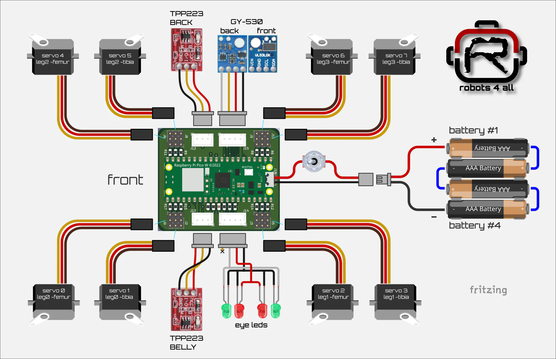
The best way to supply the servo motors with power is directly from the battery. And if there's a way to get around DC/DC converters for the microcontroller even better - the best component is the component we can spare. It will reduce cost and complexitiy. For that reason, RoBug is powered from a 4s NiMh AAA battery with a voltage range of 4.8V to 5.6V, just perfect for the Raspberry Pi Pico 2W. And there are many servo motors on the market that will happily accept the same voltage range. Very straight forward - the only thing else we need is a power switch. Check out the wiring diagram below
Actuators- power supply: the actuators will be powered direcly from the battery. Assuming a 4xAAA NiMh battery pack, the input voltage range should be be around 4.8V to 5.6V.
- torque: RoBugs tibia is about 110mm long. Assuming a total weight of 350g With only two feet on the ground during the swing phase, about 2kgcm will be required. For dynamic motions the actuator should exceed this minimum value
- speed: to enable a really quick swing back phase, the angular velocity should be around 0.1s/60°, the quicker the better.
- weight: There will be 8 actuators total, so low weight is important to keep the overall weight of the robot low. Also there will be an actuator sitting in the knee joint of each leg. This will add to the inertia of the hip joints which is bad for quick and dynamic movements. Long story short: Actuators should be as light weight as possible.
- size: Four actuators will sit in the body enclosure where space is a precious resource. The remaining four actuators will be placed in the knee joints and should be small enough to fit into the targeted leg design
- construction: the actuator shaft will be exposed to radial forces generated by the body mass of the robot. So we definitely want a metal shaft and metal gears with proper bearings for durability and robustness.
Surprisingly enough, a very good actuator choice is the very well known and widely available and affordable MG90S servo. It delivers a stall torque of 2.4kgcm, achieves an angular velocity of around 0.1s/60° with a weight of 15g.
Noname MG90S servos worked surprisingly well in the RoBug prototype. But if budget allows and you are planning to work with RoBug intensively, I recommend TowerPro MG92B servos or at least the original TowerPro MG90S types. They are fast, strong, precise, durable and worth the additional money. And I noticed that they have way less backlash compared to cheaper servos. No - I'm not sponsored by TowerPro ... to my regret ;o)
Let's build a RoBugSo here's the internal wiring plan, really not that difficult, especially if you decide to use the RoBug Base Board PCB.
RoBug Base Board PCB: If you opt in for the PCB, download the RoBug Base Board KiCad project, generate the manufacturing data and order the PCB from your favorite PCB manufacturer. Once you have the PCB on your workbench, start with soldering on the 0805 SMD components. After the SMD components are done, proceed with all the headers, connectors and other THT parts. Instead of soldering the Raspberry Pico 2 WH directly into the board, use two 1x20 standard 100mil female headers to the left of J16 and to the right of J17. J16 and J17 stay unpopulated, they provide access the Raspberry Pi Pico 2WH GPIOs for custom wiring. As you can see in the schematic and on the PCB, there's a footprint for an optional ST LSM6DSL IMU. This IC requires advanced soldering techniques, so just leave it alone for now.
Option: Prototyping Board
Optionally, if you want to save a few bucks or you just feel like soldering, you can use a 56mm x 50mm piece of prototyping board instead of the PCB. Place the connectors roughly like they are placed on the RoBug Base Board and wire up the connections using silver coated copper wire and a few pieces of cable. Actually that's what I did for the prototype. You can refer to the simplified schematic below.
Here's my take on the prototyping option for the base board. I used it for the RoBug prototype and it works like a charm and is still in use as I write up this project :-)
Battery
Now it's time to assemble the battery. The four 800mAh AAA NiMH batteries from the part list have solder tags, Solder them together as depicted in the wiring diagram but make sure you get the orientation right. IF YOU MAKE A MISTAKE HERE YOU COULD DAMAGE THE BATTERIES OR EVEN HARM YOURSELF - so be careful here!
Cut the 1x2 female JST cable from the part list to a length of 8 - 10cm, then solder the black wire to the negative pole of batterie #1 and the read wire to the positive pole of battery #4. Wrap the batterie pack in insulating tape to give it some structural stability but don't go crazy here, not more than one layer of tape to avoid overheating of the batteries.
Use the rest of the cable, the power switch an the 1x2 male JST header to build the counterpart of the battery cable. Make sure you solder the red and black wire to the correct pins of the male JST header as shown in the wiring diagram above. Cut the red cable in half and connect the power switch to the two halves as shown. When soldering the male JST connector to the cable, work fast and precisely, otherwise the hot pins will melt the plastic of the header housing and become lose. Oh, and I highly recommend to protect all the soldered connections with some small pieces of heat shrink tubing.
GY-530 distance sensor:
Take one of the 1x4 female JST cables from the part list and cut it to a length of 10 to 12cm. Solder the cable to the GY-530 distance sensor as shown in the wiring diagram, Make sure you solder the cable into the sensor PCB from the BACK and that the solder pads are flush with the front PCB surface. Keep the GY-530 front side as even and flat as possible, you'll appreciate that when you mount the sensor into RoBugs head. You'll find pictures of the prototype assembly below. (I used different cable colors, but you can stick to the wiring plan)
GY-530 and LED assembly :
ok, this is a little bit more manual work and it requires the 3d printed front cover insert to be available. So if you don't have the 3d printed parts yet, go to the 3d printing section and come back once you have printed all theRoBug parts.
Assuming you have the front cover insert ready gently push the pre-assembled GY-530 into the rectangular cavity so that the VL53LX0 sensor on the front of the PCB can "look" through the hole in the insert.
Next, push the four LEDs into the insert as far as possible. BEFORE you do that, make sure the cathodes (shorter legs) of each LED pair are pointing towards each other. Make sure the colors are in the correct positions. If the fit of the 3mm holes in the insert is to tight you can widen them carefully with a 3mm drill.
Now shorten the LED legs to about 5mm or a little less. Solder together the two cathodes of each LED pair. Then connect the anodes of the left and right green LEDs with a short piece of cable, followed by the anodes of the left and right red LEDs and finally the common cathodes of the left and right LED pairs. Now we have a common cathode for all four LEDs, a common anode for the red LEDs and a common anode for the green LEDs.
Eventually, take a 1x4 female JST cable and shorten it to 10 to 12cm. The yellow wire will not be used at all so you can remove it completely. Now solder the black cable to the common cathode, the yellow wire to the common anode of the red LEDs and the white wire to the common anode of the green LEDs as shown in the image above.
TPP223 capacitive touch sensors:
Take one of the 1x3 female JST cables from the part list and shorten it to about 10 to 12cm. solder the wires into the TPP223 PCB as drawn. Again, make sure you solder the cable into the sensor PCB from the BACK as shown. Proceed exactly the same way with the second TPP223.
All the STL files and the Blender design file (yes, correct, RoBug was designed with Blender) are are available for download. I added some screenshots to show how I arranged to parts on the 3d printer plates. The RoBug stand and the calibration gauge on plate 3 are optional but super helpful if you intend to develop your own gaits and motions. I printed everything with Babulab PLA Matte Ivory White on a smooth printing plate.
The only parts that need some supports for a good looking result are the front and rear covers, the front cover insert and the stand. The image below shows how the sliced results of the front and rear cover looked for me - the white dots/lines are the seams. I recommend to keep them away from the cutouts for a good looking printing result. All the other parts are easy to print and straight forward.
When you finally have all the required parts on your desk, you are ready for assembly. Just follow videos below, they will guide you through the assembly process step by step.
servo and sensor connectors:
When plugging in the servo connectors. make sure the brown wires point outside while the yellow wires point inside.
The RoBug firmware was completely written in MicroPython, which is a Python version tailored for smaller SBC and MCUs. It provides support for all the typical microcontroller peripherals such as PWM, ADC, I2C, UART, even WiFi and Bluetooth. Obviously, to make this work, the correct MicroPython version needs to be installed. The latest version is available here: Raspberry Pi Pico 2W MicroPython. Download the file to your computer, we'll need it in a minute. Now connect a USB cable to the Pico 2W but don't plug it into your computer yet. Press the little white button on the Pico 2W and, while holding it down, plug in the USB cable to your computer. The Pico appears as USB mass storage device in the file browser. Now simply copy the .uf2 file you just downloaded to the Pico. That's it - next time you power up the Pico, it will start in "MicroPython mode" automatically.
There are many IDE options around but I really recommend the open-source IDE Thonny to get started. Download Thonny and install it on your computer. With the prepared Raspberry Pi Pico 2W connected over USB, start Thonny and select "MicroPython (Raspberry Pi Pico) Board CDC @ COMx" as the Interpreter (bottom right corner of the Thonny window). Thonny will establish a connection to the Pico and you should see a status message similar to the one in the image below in the Thonny shell tab:
To eventually install the firmware on your RoBug either download and unpack the RoBugFW.zip file from the download section or clone the RoBug git repository to your computer. I recommend the git option since the firmware is under continuous development and the latest version will be on git only. Now open Thonny, go to "view" and check "Files". In the "Files" tab navigate to the folder in which you unpacked/cloned the firmware python files. Now you should find all listed in the "Files" tab like below.
Next, connect RoBug to the computer via USB. A second tab will open in the "Files" section that shows what's stored on the Pico. Since we only installed MicroPython itself and nothing else yet, this tab is empty. But not for long.
Select all the files in the the source folder of the computer, right-click and select "Upload to \". This will transfer all the file to the flash memory of the Pico.
A few seconds later, the "Files" tab should look similar to this - alle the files were transferred to the Pico, the firmware is installed.
Before you can run the RoBug firmware, the two additional MicroPython packages 'copy' and 'aioble' need to be installed on the Raspberry Pi Pico 2W. Simply search for the packages in Thonnys package manager and hit the 'install' button.
RoBug applications are named robug_app_[appname].py.
- robug_app_led_test.py: super simple smoke emission test. RoBugs leds will be turned on and off smoothly in an endless loop. If this programm is running without problems you should be all set up.
- robug_app_template.py: It demonstrates how the RoBug software framework can be used to write custom applications
- robug_app_explorer.py lets RoBug explore his environment autonomously. RoBug will avoid obstacles using the distance sensor readings.
- robug_app_rc.py: works in conjunction with the RoBug Remote Control smartphone app. It let's you control your mechanical friend with your smartphone. Will take a closer look at this in the next chapter.
You can load and execute any of the applications in Thonny. However, after power-on, RoBug will always execute the MicroPython file main.py. After the firmware is installed, main.py will be a copy of robug_app_template.py.
To test if everything works as expected, put RoBug on its stand, remove the USB cable and turn on the power switch. The robot should do a few forward and a few backward dry steps. Congratulations - your RoBug is up and running :-)
If you want to change what is executed after power-on, you need to overwrite main.py with the intended application. So don't forget to make backups regularly! E.g. to make RoBug explore your room autonomously, connect the robot to the computer via USB, load e.g. robug_app_explorer.py in Thonny and save the code as main.py. Next time you switch on power, RoBug will start to crawl around all on his own.
And if you are interested in how the firmware works and how you can code your own RoBug application check out the RoBug framework documentation on github.
RoBug Remote ControlI soon felt that I needed a way to r/c-control RoBug to test out how different gait tunings work, to debug sensor code and to test mechanical updates. So I came up with the RoBug RC smartphone app. Since I have zero experience in application development on android or iOS, I implemented the app in MIT App Inventor. It is easy to learn and it is platform agnostic, so one can build apps for android as well as for iOs from exactly the same source.
Communication between the smartphone and RoBug is implemented using Bluetooth Low Energy (BLE). Your phone needs to support that to run the remote control app. Note that GPS needs be turned on for BLE to work - and no, I don't know why ;-)
There are two ways for installation:
- those who are familiar with MIT App Inventor can download RoBugRC.aia from git, import it to MIT App Inventor and build the app for your target platfrom. Note that you have to install the BLE extension in MIT App Inventor to make the app work.
- if your phone happens to run on android (>5.0), you can directly download RoBugRC.apk from git and install it on your phone. Several security warnings will pop up during the installation and it's a good idea to let the phone scan the app for viruses and malware - I pledge that I didn't hide anything malicious in the RoBugRC app but I simply can't guarantee for the security of the hackster.io servers... no offense, hackster ;-)
On the RoBug side, use Thonny again to save robug_app_rc.py as main.py. Remove the USB cable and turn on the power switch. RoBug will stand up and stand still, waiting for a BLE connection.
Start the RoBugRC app on your phone, and click the bt scan button.
Find RoBug in the list of BLE devices and click on it.
When the BLE connection was established successfully, the app will show that it is connected to RoBug and the distance to the next obstacle will be updated every 500ms (will show 8191 if nothing is close enough to detect it).
You are ready to for the first ride with RoBug. Even though this app started as a debug tool it is so much fun ;-)
You may wonder what the start FPV button does?
Spoiler: I'm working on an add-on to stream live video from RoBug to the remote control app to turn the robot into a tiny legged fpv drone, so stay tuned...
Even though we payed attention during assembly, it will be necessary to calibrate RoBugs joints to make sure all four leges move synchronously. The easiest way to do this is to use the calibration screen of the RoBugRC. To go there, just click on the "next page" button on the bottom right corner of the screen.
The app works in conjunction with robug_app_calibrator.py on the RoBug side. Simply put RoBug on its stand, load the python file in Thonny and execute the programm. RoBug will assume its calibration. pose. If you didn't do so yet, connect the app to RoBug as before. Make sure the "offset" button is checked, the "gain" button is not functional yet. Now you can use the plus/minus buttons to adjust each of the eight joints until the upper and lower legs are perfectly square. To simplify the alignment of the leg joints, you can use the calibration tool that is included in the stl files. Place the calibration tool on top of the stand and RoBug on top of the calibration tool like in the images below. Now adjust the joint alignment using the RoBugRc app until all the four femurs and tibias gently touch their respective contact points.
Hit the save button to save the new calibration values to RoBug. When RoBug is powered on the next time, the new calibration values will take effect.
A few final wordsI made everything that belongs to the RoBug project open-hardware/open source. I'm sure you understand that lots and lots of time and work went into this project. So please honor the licenses under which this project is published, only then open-hardware/open-source projects like this will have a future. If you decide to build a RoBug and you want to do me favor... post an image or a short video.
I can't wait to see what you guys create.
A big shout-out to David for providing tons of precious feedback!
Licensing- the RoBug documentation on this hackster.io page, the videos and the images are licensed under CC BY-SA 4.0
- all RoBug hardware design files (blender, pcb, schematic, stl etc.)
are licensed under CERN-OHL-W v2 - the RoBug software (firmware, MIT App inventor application)
is licensed under GPL v3


Comments