


Hardware components | ||||||
| × | 2 | ||||
| × | 1 | ||||
| × | 1 | ||||
Software apps and online services | ||||||
 |
| |||||
Hand tools and fabrication machines | ||||||
| ||||||
Generally, the touch sensor is made with help of capacitance of two plates which varies according to the distance between those plates. but the principle of working of this is different. it works on the resistance variation due to moisture of fingers as shown in the last fig.
We can use these sensors for moisture detection in the soil as well as rain detection. the circuit diagram, require components, equipment, steps are given below;
Required Equipment’s:-1) Soldering Iron
2) Holder stand
3) Stripper
Required components:-
1) UTSOURCE Transistor x 2 (BC547)
2) Zero PCB
3) Wire
4) UTSOURCE LED (LED)
5) Resistor
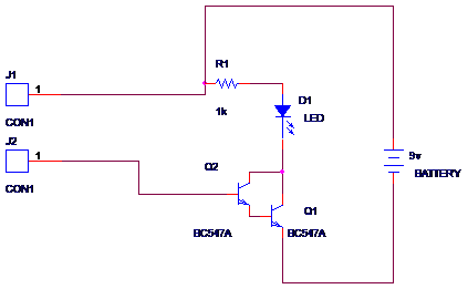
Below fig. shows a circuit diagram of the touch sensor by using a transistor. Here, we have used two-transistor which are coupled in Darlington pair which increases the gain of the whole circuit that will help us to amplify the signal generated by the VCC. Led is connected to connect to the collector of the transistor through 1 k resistor. 1 k value of the resistor will avoid damage of LED in short circuit level. the base of the transistor is connected to the touch region.
Step 1)
Mount transistor on PCB according to the circuit diagram. Place two-transistor on PCB as shown in fig. and solder it with the help of holder stand. Make sure that you have connected it is connected in Darlington pair.
Step 2)
Connect led to the collectors of the transistor. you should use a current limiting resistor to avoid damage to the LED. Here, I have used the 1k value of resistor as the current limitation.
Step 3)
Make touch region by using soldering wire as shown in fig. you can use wire also for it, you can solder on it. The two-wire should be separated from each other.
Step 4)
Connect touch region to the base and VCC supply of battery as shown in fig.
Step 5)
Connect 9v battery to the given constructed circuit. the negative terminal is to the emitter and the positive terminal is to another end of resister as shown in the circuit diagram.
Now, It is ready to test. Just put your finger on the touch area then it will work as shown in the figure. the first fig. shows that finger is not on sensor thus led is not on. the second fig shows that the figure is on sensor thus led get on.
You can observe that we have applied a positive voltage supply to the sensor through the wire ( +vcc ) another terminal is connected to the base of the transistor. also we have used Darlington pair. We should note that our hand has very high resistance but it is sufficient to pass microamps of current. Now, when touching the sensor that time the current start flowing through our finger to the base of the transistor. the amount of current applied to the base of the transistor is in the range of microamps. the first transistor amplifies it by factor-beta and it is applied to the base of the next transistor thus again it gets amplified by a factor of beta. thus overall amplification is very large thus transistor goes in saturation region and it acts as a switch which turns on-off the led. it can respond when any moisture is present thus we can use it as a rain sensor also, as well as we can use it in moisture sensors in the soil which will be used for on-off the motor by using microcontroller such as atmega328, atmega168.
We have learned how to make the simplest touch sensors by using two transistors. if it is not working properly it means that it is shorted in the touch region or it contains shorted transistors or led is damaged. thus use proper component by checking it. also then it is not working then the battery may be discharged if it is discharged then replace. the value of the battery is should be 9 v but you can use 12v also and 6 v also. it is on you which supply you have. but it is not working on ac supply.


Comments