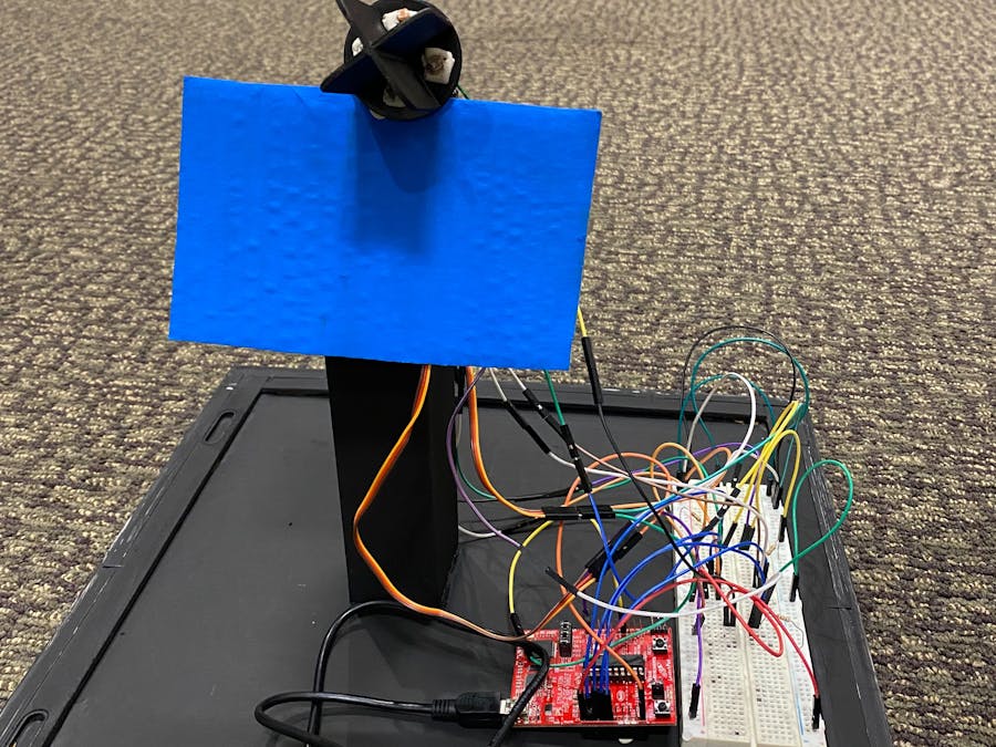
This project consists of a solar panel tracking that basically tracks the position of the Sun, It is a dual-axis that moves from Up to Down and Right to Left, enabling the way to get as much sun as possible and for future implementations this project can help the user to save as much energy as possible.
I decided to create this project because solar energy is important because it helps the environment. So, by implementing this project the energy can be saved in a better way.
Created for Embedded Systems Class Fall 2022
John Brown University, Engineering Department
Here are some images of the final version of the project.
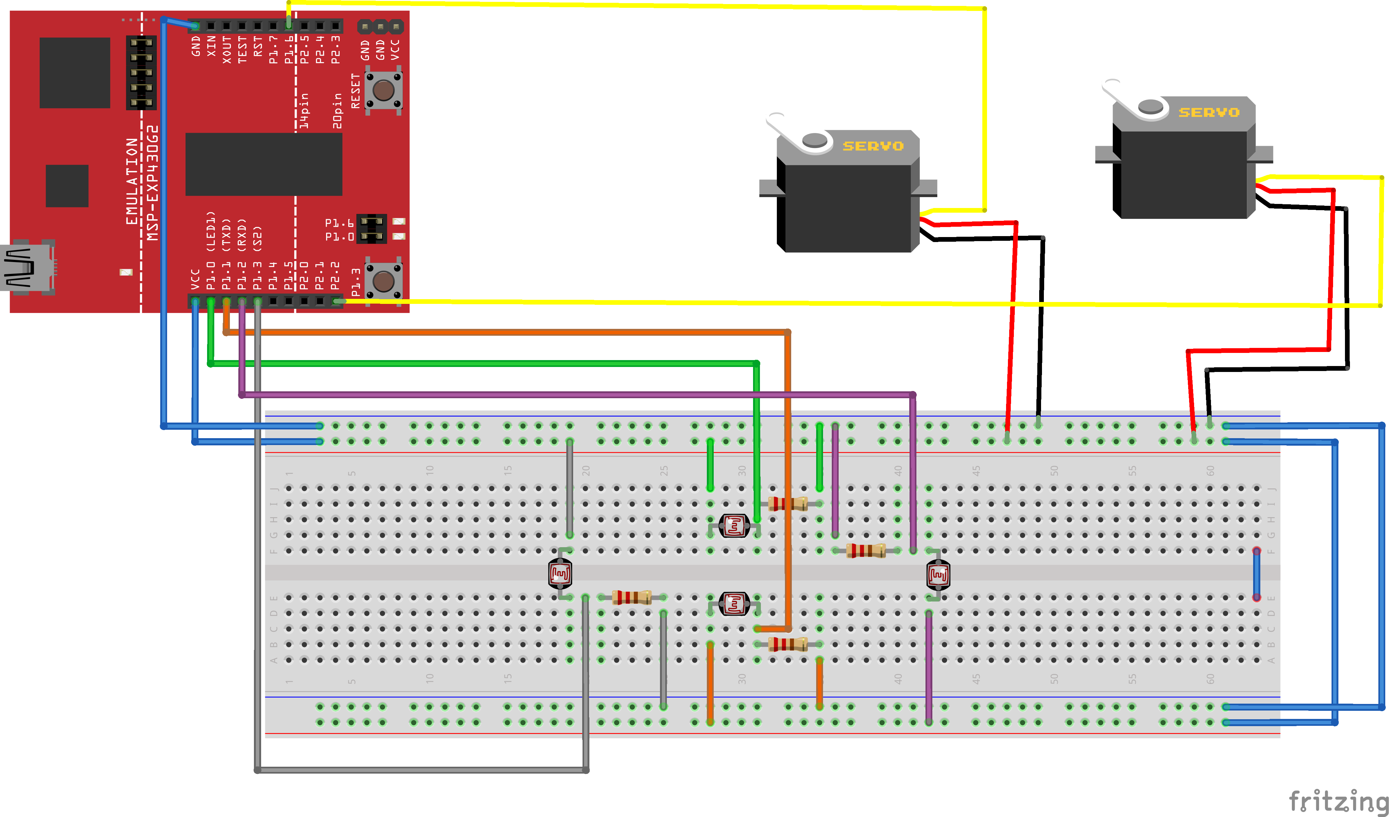
Diagram created in fritzing.com


Comments