


Hardware components | ||||||
| × | 1 | ||||
 |
| × | 1 | |||
| × | 1 | ||||
| × | 1 | ||||
| × | 1 | ||||
| × | 3 | ||||
| × | 1 | ||||
| × | 1 | ||||
| × | 1 | ||||
| × | 2 | ||||
| × | 1 | ||||
| × | 1 | ||||
| × | 1 | ||||
Software apps and online services | ||||||
| ||||||
| ||||||
 |
| |||||
Hand tools and fabrication machines | ||||||
 |
| |||||
 |
| |||||
 |
| |||||
| ||||||
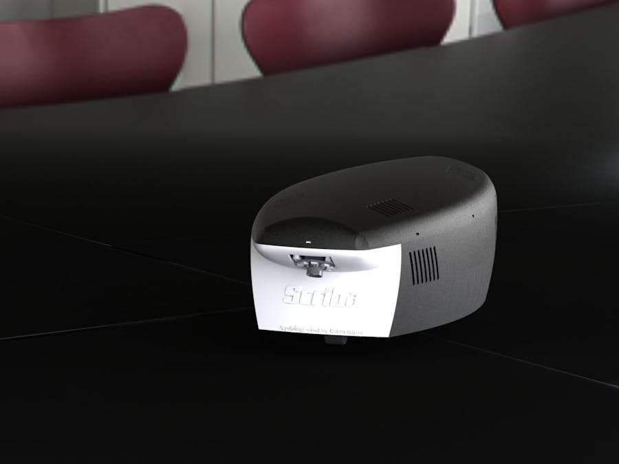
Scriba is a printing robot. It prints on its wake, using the sheet edges and the printing in process as a reference for its navigation. It uses multiple cameras to correct its trajectory and printing alignment through a SLAM (Simultaneous Localization And Mapping) algorithm.
I'm well aware that this system has no real advantage over a foldable mini-printer but I wanted to make a cool project to practice a bit with stepper motors and to work on a camera SLAM with OpenCV.
The robot was supposed to be light and portable but grew in sized as the project progressed. It is designed to print on medium and large surfaces.
WORK IN PROGRESS
Done:
- Mechanical design
- Electrical design
- Components printing/machining
- Robot assembly+ PCB assembly
- ROS serial communication with Arduinos
- Standard motor command
- Odometry
- Odometry and motor command calibration
To do:
- Printhead test
- Low voltage disconnect board
- Step motor command
- Printing command
- Localization by camera
The robot was designed using a CAD software. Most of the components are 3D-printed.
Mechanical components such as ball bearings, screws, gears... were bought in DIY retail store or on internet. The wheels are from DIY retail store and are normally intended for furniture building.
The two motor shafts were supposed to be 3D-printed but it was impossible to get the required accuracy. I fortunately got access to a lathe and was able to machine them.
I couldn't get a gear as big as I needed for a component (gear link between the motor and the middle part). So I decided to machine it and obtained good result by laser cutting it.
Circuit schematics and PCB were designed with EAGLE and then tested with a breadboard.
Once the design tweaked according to the tests, I ordered the PCBs to a PCB manufacturer.
This is the first I use this kind of service and I appreciate the quality very much. It is really nice to be able to get professional-quality PCBs.
PCBs were then mounted on the robot using spacers:
Controls
The main computer of the robot is an Odroid-XU4 running Ubuntu 18.04 and mainly relying on a ROS (Robot Operating System) program to run the robot. Computer vision tasks are carried out by OpenCV programs interfaced with the ROS main program.
Actuator control is carried out by two Arduino Nanos, as they can handle real-time operation and GPIO control better than the main computer. They are connected to serial node on the ROS main program.
The robot can be controlled by WiFi from a remote computer by connecting to the Odroid-XU4 via SSH.
Drive Configuration
The robot has a steer drive configuration (also called steerable driving wheel configuration) with one powered and steering wheel at the front and 2 wheel for support at the rear (like a tricycle). This configuration was chosen because of the high driving accuracy it provides when following a navigation path.
Navigation & Localization System
The robot uses a SLAM algorithm (Simultaneous Localization And Mapping) to navigate. It localize itself by using the printing in process as a reference.
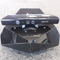
Cameras are located at the front and at the rear of the robot. Their location allows the robot to see the printing in process (with the rear camera) and the previous printing. Being able to see the previous printing after a turn is crucial to correct localization because turns generate a lot of imprecision in the odometry.
A light source near the camera ensures a correct and uniform lighting of the scanned surface. Inclination of the camera images is corrected by a homographic algorithm.
Printing system
The printhead is placed on a sweeping system. Both have to stay perpendicular to the printing direction even when the robot is correcting its trajectory. The printing system is therefor able to rotate around the kinematic center of the robot.
Overall Design
The traction and steering motor are assembled in a “drive unit” placed at the front of the robot.
The driving wheel is powered by a stepper motor (14HR08-0654S) with a step angle resolution of 0.9 deg. In addition an encoder counts the rotation angle with a resolution of 1.8 deg.
The driving wheel is steered by a stepper motor (14HR05-0504S) with a step angle resolution of 0.9 deg. In addition an encoder counts the rotation angle with a resolution of 1.8 deg. The system is designed to rotate the driving wheel +/-90°.
Taking in account gears and microstepping configuration (rms), the relation between steering motor step and wheel angle (phi) is:
To recap the possible results:
Two microswitches are used to detect the end position for calibration purposes: the starting angle of the wheel is unknown and a calibration is required before driving the robot. The microswitches are placed on slotted holes and can be adjusted.
Electronics
The stepper motors are controlled by an Arduino Nano and two A4988 modules. All those elements and connections for encoders, microswitches, and so on are integrated into a PCB (named “Steering Board”).
The board needs 5V and 8.5V power supplies. The5V can be supplied by the Arduino if the Arduino power supply jumper is connected.
Microstepping Selection
Stepper microstepping can be configured by the use of jumpers on the board. Connecting a jumper sets the microstep pin to high.
The truth table for the MS pins logic is the following:
Emergency Stop
An emergency stop feature prevents the motors from running without a 5V input on the emergency stop connector. The emergency stop red LED lights when the signal is absent.
Program & Control
The unit is driven by an Arduino Nano. The Arduino is connected to the main computer of the robot, the Odroid XU4 by USB.
The program on the Arduino connects to a serial node of the ROS main program.
Printing SystemOverall Design
The printing system is assembled on a rotating support (rotating around the robot kinematic center) to correct the alignment if needed.
The printhead is placed on a “slider”, giving the system an 83mm sweeping length. The slider is powered by a stepper motor (DC 4-9V Drive Stepper Motor Screw With Nut Slider 2 Phases 4 Wires) with a resolution of 0.18°/step. The endless screw has a resolution of 0.5mm/turn making the overall system to have a resolution of 0.025mm/step.
Taking in account the microstepping configuration:
Two microswitches are used to detect the end position for calibration purposes. The starting position of the stepper motor is indeed unknown and needs to be calibrated.
Printhead
The printhead used by the robot is an inkjet printhead HP 51604A. It has been chosen for its ease of use and low price. Hacked inkjet printhead with easy controls are difficult to find. The HP 51604A (and the HP C6602) have a good documentation available online.
Most information on how to control the printhead came from Inkjet Printer For the RepRap by Amberish Jaipuria (https://reprap.org/mediawiki/images/1/1a/Inkjet.pdf), itself using as a primary source Inkjet Applications by Gilliland, M.
The printhead can only print in one color(black) with no possibility of half-toning. The printhead features 12 nozzles spanning over 3.2mm.
Each nozzle has a 65Ω resistor and fires when a pulse is put across the resistor. The total energy released during the pulse has to be around 40µ Joules.
Taking in account the following equation:
Gilliand M. calculated the optimal pulse widths and voltages and provides the following table:
Those pulse width are optimal. A too short pulse time can result in low droplet quality or clogged nozzles. A too long pulse time can burn the nozzle resistor.
It’s also recommended to wait at least 800µs before firing again the same nozzle. Two adjacent nozzles cannot be fired simultaneously and only two nozzles on the whole printhead can be fired simultaneously. Moreover it is recommended to wait 0.5µs between each nozzle pair being fired.
A PCB (“Printhead Contact Board”) allows for a stable and easy connection between the nozzle contacts and the wires from the controller.
Wires for contacts are soldered and guided through the holes of the PCB.
Printing slider
The printhead is placed on a slider, allowing the printing pass to be wider. The slider includes the printhead and its contact board, as well as a camera for shift and misalignment detection.
The camera height and angle can be adjusted by two screws. The camera is an ELP USB camera with a 2.1mm objective (ELP-USBFHD01M-L21). Objective value was chosen using a focal length calculator.
Alignment & Correction
The printing system needs to correct the eventual robot misalignment and shift from the intended position to ensure a good print quality. This error correction can be split in three items
- Forward/backward drift
- Lateral drift
- Alignment
Forward/backward drift
There is no actuator for correcting an error in the printing direction (robot driving direction). The system relies instead on “shifting” the nozzles used. A least 1 nozzle on each end of the printhead needs to be reserved for this operation and therefore reduces the overall nozzle span.
Lateral drift
Lateral drift is simply corrected by adding an offset on the slider starting position. A specific length on both sides has to be reserved for this operation and therefore reduces the slider course.
Alignment
The printing system can rotate slightly around the robot kinematic center to correct its alignment. A servomotor is used to control the rotation. The gear ratio between the servomotor and the printing system is 18/244.
Electronics
The printhead nozzles are controlled by two ULN2803 Darlington arrays to interface the Arduino outputs with the 20V power supply. For each nozzle a pull-down 1kΩ resistor is added to ensure a good control of the firing pulse time.
The stepper motor for the slider is controlled by an Arduino Nano and an A4988 module.
All those elements, as well as the 20V power converter and the connections for the end position microswitches are integrated into a PCB (named “Printhead Control Board”).
The board needs 5V and 8.5V power supplies as well as a connection to the battery. The 5V can be supplied by the Arduino if the Arduino power supply jumper is connected.
Microstepping Selection
Stepper microstepping can be configured by the use of jumpers on the board. Connecting a jumper sets the microstep pin to high.
The truth table for the MS pins logic is the following:
Emergency Stop
An emergency stop feature prevents the motors from running without a 5V input on the emergency stop connector. The emergency stop red LED lights when the signal is absent.
Program & Control
The unit is driven by an Arduino Nano. The Arduino is connected to the main computer of the robot, the Odroid-XU4 by USB.
The program on the Arduino connects to a serial node of the ROS main program.
Localization SystemScriba robot uses two cameras for its localization. They are placed at the front and rear of the robot on a rotating support for easy adjustment. A LED ring provides good and adjustable lighting conditions.
The cameras used are ELP USB cameras with a 2.8mm objective (ELP-USBFHD01M-L28). Objective value was chosen using a focal length calculator (closest value available).
Three different voltages are used by the robot components: 5V, 8.5V and ~20V. Power is provided by a 3S battery (Black Lithium 11.1V 1500mAh) and then converted and distributed to the different elements.
The battery and converters are placed at the rear of the robot to keep the majority of the weight as close as possible to the kinematic center to minimize drift.
A first board connects to the battery and distributes the power to the power converters and battery level display. The output power from the power converters (5V and 8.5V) is then supplied to another PCB (“named PowerOut” or “Power Distribution Board”) with screw terminals for easy distribution to other elements. This board also includes a 1000µF capacitor on each voltage to smooth current spikes.
The battery board will be replaced by a LVD (Low Voltage Disconnect) board with a relay/transistor in the future.
Robot ModelBefore implementing any navigation feature, the robot needs to be modeled. The model is not only useful for visualization purposes but also essential for frame transforms and other calculations.
For a ROS implementation two models are needed:
- Kinematic model: needed for odometry and move command.
- CAD model (URDF): base on the kinematic model, needed for visualization and frame transforms.
Kinematics
The kinematics equations of the robot are needed to implement move command and odometry.
If you are not allergic to math, all kinematic equations are described in the document “Kinematics_Scriba.pdf” in the attachments.
URDF
ROS uses URDF (Unified Robot Description Format) files to describe robot models. Those models are described using a kinematic logic, with “links” (parts) connected through “joints” of different types (rotation, translation …).
The URDF file and other files needed for visualization are included in the ROS package “scriba_description”.
NavigationCalibrationAn accurate model is essential for odometry and navigation commands. The model therefore needs to be calibrated to ensure an optimal navigation.
The three variables to calibrate are:
- Front wheel angle offset
- Front wheel radius
- Robot’s length (distance between the kinematic center and the front wheel)
All values are dependent on each other and as such it is possible to get a better calibration by repeating the operations a second time.
Front Wheel Angle Offset
Before calibrating the front wheel angle offset it’s necessary to run a script to put the wheel at position zero.
The robot main program is launched first using the bringup launch file:
roslaunch scriba scriba_bringup.launch
And the following script is run on another terminal (0 as wheel offset):
rosrun scriba scriba_front_wheel_calibration.py
The robot can then be placed on a straight and visible line (on a floor pattern for example) and driven in a straight line using the teleop keyboard.
By using the following equation (from the document “Kinematic_Scriba”) the front wheel angle can be calculated and corrected by an offset:
dwr being the reported x-displacement in the odometry in this situation.
Front Wheel Radius
Once the front wheel angle calibrated the wheel radius can be calibrated as well.
The robot main program is relaunched first using the bringup launch file:
roslaunch scriba scriba_bringup.launch
And the following script is run on another terminal (with the previous calculated offset as wheel angle offset):
rosrun scriba scriba_front_wheel_calibration.py
The robot can then be placed on a straight and visible line (on a floor pattern for example) and driven in a straight line using the teleop keyboard.
The calibrated wheel radius is given by the following formula:
Δx_odometry being the reported x-displacement in the odometry.
Δx_real being the measured x-displacement
Robot’s Length
At last the robot’s length value needs to be calibrated. Length refers here to the distance between the front wheel and the robot’s kinematic center.
The robot main program is relaunched first using the bringup launch file:
roslaunch scriba scriba_bringup.launch
And the following script is run on another terminal (with the previous calculated offset as wheel angle offset):
rosrun scriba scriba_front_wheel_calibration.py
The robot can then be placed on a straight and visible line (on a floor pattern for example) and driven in circle using the teleop keyboard (maximum rotation: front wheel angle of π/2 to rotate around the kinematic center).
The calibrated length is given by the following formula:
ωodometry being the reported z-angle in the odometry (be careful, angles are reported as quaternion in ROS).
ωreal being the measured angle.
OdometryThe odometry (or “dead reckoning”) refers to the estimation of a robot position through its motion sensors data. The odometry is a relative position estimation (relative to the starting position) and suffers from the accumulation of sensor uncertainties, preventing it from being efficient over a long time period. Odometry is often use in combination with an absolute position estimation (such as a camera using external element as reference points).
In Scriba, the odometry is computed by the main computer with data from the Arduino of the drive unit. The node “scriba_odometry_broadcaster” in the “scriba” package subscribes to the topic /data_odom to receive the odometry data.
The odometry data is transmitted on the topic in a custom message type “odom_data” (from the “scriba_msgs” package)including:
- Time stamp
- Front wheel angle (at the beginning of the sample)
- Front wheel angle (at the end of the sample)
- Front wheel traveled steps
- Sample duration
The position is estimated using this data and the previous position.
The odometry data currently uses only stepper motor commands. Encoders are wired but not yet used due to the limited memory available in the Arduino Nano of the drive unit. They will be added if the odometry quality needs to be improved.
LocalizationThe localization refers to the absolute position estimation (using external references) used to correct the odometry position estimation.
WIP – Algorithm is not finished yet.
Move CommandsTwo drive modes are used by the robot:
- Standard mode, used when turning and moving to the next printing position.
- Printing mode, used when printing: low speed and steps command.
WIP – Printing mode not implemented yet.
Acknowledgements & Sources- Interface A4988 Stepper Motor Driver Module with Arduino
- Inkjet Printer For the Reprap by Amberish Jaipuria
- DIY Inkjet Printer by Patrick Hannan, Jared Knutzen, Nicholas C Lewis, Joy Markham


Comments