


Hardware components | ||||||
| × | 1 | ||||
 |
| × | 1 | |||
| × | 1 | ||||
| × | 1 | ||||
| × | 1 | ||||
| × | 1 | ||||
| × | 1 | ||||
| × | 1 | ||||
| × | 1 | ||||
| × | 1 | ||||
| × | 1 | ||||
| × | 10 | ||||
| × | 1 | ||||
| × | 1 | ||||
Software apps and online services | ||||||
 |
| |||||
| ||||||
| ||||||
| ||||||
| ||||||
| ||||||
Hand tools and fabrication machines | ||||||
 |
| |||||
| ||||||
| ||||||
| ||||||
| ||||||
| ||||||
| ||||||
| ||||||
| ||||||
The STM32F103C8T6 is one of the most popular low-cost ARM Cortex-M3 microcontrollers used on small development boards commonly known as the Blue Pill.
It is inexpensive, compact and considerably more capable than a basic 8-bit microcontroller. The STM32F103C8 family can operate at up to 72 MHz and provides 64 KB or 128 KB of Flash depending on the device variant, 20 KB of SRAM, 12-bit ADCs, timers, PWM, I²C, SPI, USART, USB and CAN.
Instead of making another LED blink project, I wanted to build something that demonstrates how these peripherals can work together in a small embedded control system.
The result is a simple automatic temperature-controlled fan controller.
The basic idea is:
- Measure the ambient temperature.
- Show temperature and humidity on an OLED.
- Calculate an appropriate fan speed.
- Generate a PWM signal for the fan.
- Send measurements to a PC through UART.
- Increase cooling automatically when temperature rises.
This is a useful pattern for many embedded applications, including:
- enclosure cooling
- small electronics cabinets
- 3D-printer electronics
- network equipment
- DIY instruments
- power-electronics prototypes
- laboratory equipment
- battery-powered equipment
The DHT22 provides temperature and humidity data to the STM32F103C8T6.
The firmware then converts the measured temperature into a target fan speed.
For example:
Temperature
Fan PWM
< 25°C
0%
25–30°C
30%
30–35°C
50%
35–40°C
75%
> 40°C
100%
This isn't intended to be a precision thermal-control system. The temperature thresholds are deliberately simple so that users can modify them for their own enclosure or cooling application.
The OLED continuously displays something similar to:
STM32 COOLING
Temp: 31.4 C
Hum : 58.2 %
Fan : 50 %
Status: COOLING
STM32 COOLING
Temp: 31.4 C
Hum : 58.2 %
Fan : 50 %
Status: COOLING
At the same time, the STM32 sends the measurements through UART:
Temperature: 31.4 C
Humidity: 58.2 %
Fan PWM: 50 %
Temperature: 31.4 C
Humidity: 58.2 %
Fan PWM: 50 %
This makes it easy to observe the system from a PC during development.
Why STM32F103C8T6?The interesting part of this project is not simply the temperature sensor.
It is the fact that a relatively small MCU can coordinate several peripherals simultaneously.
The STM32F103C8T6 provides:
- 72 MHz Arm Cortex-M3 CPU
- 64 KB Flash for the C8 device
- 20 KB SRAM
- 12-bit ADC
- multiple timers
- PWM
- I²C
- SPI
- USART
- USB
- CAN
- SWD/JTAG debugging
These capabilities make the STM32F103C8T6 useful for learning the transition from simple Arduino-style programming toward more conventional ARM embedded development.
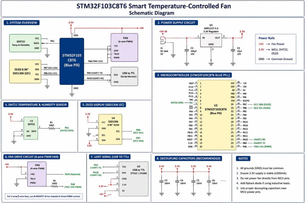
Circuit DiagramThe basic architecture is:
+----------------+
                         |    5 V Supply  |
                         +-------+--------+
                                 |
             +-------------------+----------------+
             |                                    |
          OLED VCC                             DHT22 VCC
             |                                    |
             |                                    |
      +------+-------+                    +-------+------+
      | SSD1306 OLED |                    |    DHT22     |
      |              |                    | Temperature  |
      | SDA ---------+------------------->|              |
      | SCL ---------+                    | DATA         |
      +------+-------+                    +-------+------+
             |                                    |
             |                                    |
             +----------------+-------------------+
                              |
                             GND

                    +-----------------------+
                    |   STM32F103C8T6       |
                    |                       |
OLED SDA ---------->| PB7 / I2C1_SDA       |
OLED SCL ---------->| PB6 / I2C1_SCL       |
DHT22 DATA -------->| PA1                   |
                    |                       |
                    | PWM ------------------+-------> Fan
                    |                       |
                    | UART TX --------------+-------> PC
                    +-----------------------+
                              |
                             GND
+----------------+
                         |    5 V Supply  |
                         +-------+--------+
                                 |
             +-------------------+----------------+
             |                                    |
          OLED VCC                             DHT22 VCC
             |                                    |
             |                                    |
      +------+-------+                    +-------+------+
      | SSD1306 OLED |                    |    DHT22     |
      |              |                    | Temperature  |
      | SDA ---------+------------------->|              |
      | SCL ---------+                    | DATA         |
      +------+-------+                    +-------+------+
             |                                    |
             |                                    |
             +----------------+-------------------+
                              |
                             GND

                    +-----------------------+
                    |   STM32F103C8T6       |
                    |                       |
OLED SDA ---------->| PB7 / I2C1_SDA       |
OLED SCL ---------->| PB6 / I2C1_SCL       |
DHT22 DATA -------->| PA1                   |
                    |                       |
                    | PWM ------------------+-------> Fan
                    |                       |
                    | UART TX --------------+-------> PC
                    +-----------------------+
                              |
                             GND
For a 2-wire DC fan, do not connect the fan directly to an STM32 GPIO.
Use a MOSFET:
+5 V
                  |
                  |
               FAN MOTOR
                  |
                  |
                  +---------+
                            |
                         Drain
                       +-------+
STM32 PWM ---100R------| Gate  |
                       | MOSFET|
                 10k   |       |
GND -----------/\/\----|       |
                       +---+---+
                           |
                         Source
                           |
                          GND
+5 V
                  |
                  |
               FAN MOTOR
                  |
                  |
                  +---------+
                            |
                         Drain
                       +-------+
STM32 PWM ---100R------| Gate  |
                       | MOSFET|
                 10k   |       |
GND -----------/\/\----|       |
                       +---+---+
                           |
                         Source
                           |
                          GND
For a brushed DC fan, add an appropriate flyback diode across the motor.
For a 4-wire PC PWM fan, a better implementation is to use the dedicated PWM control input rather than switching the fan's power through a MOSFET. The exact electrical interface should follow the fan manufacturer's specification.
Pin AssignmentFunction
STM32 Pin
DHT22 DATA
PA1
OLED SDA
PB7
OLED SCL
PB6
Fan PWM
PA8
UART TX
PA9
UART RX
PA10
3.3 V
3.3 V
Ground
GND
The exact Blue Pill header labeling can vary between third-party boards, so verify the board schematic/pinout before wiring.
OLED ConnectionsFor a typical SSD1306 I²C module:
OLED       STM32F103C8T6
------------------------
VCC   ---> 3.3 V
GND   ---> GND
SCL   ---> PB6
SDA   ---> PB7
OLED       STM32F103C8T6
------------------------
VCC   ---> 3.3 V
GND   ---> GND
SCL   ---> PB6
SDA   ---> PB7
Most common SSD1306 modules use I²C address:
0x3C
0x3C
but this should be confirmed for the particular OLED module.
DHT22 ConnectionsDHT22 STM32
-----------------
VCC ---> 3.3 V
DATA ---> PA1
GND ---> GND
DHT22 STM32
-----------------
VCC ---> 3.3 V
DATA ---> PA1
GND ---> GND
Add a 10 kΩ pull-up resistor between DATA and VCC if your DHT22 module does not already contain one.
FirmwareBelow is an Arduino/STM32duino version because it is easier for you to reproduce. It assumes:
- STM32duino core
- DHT sensor library
- Adafruit SSD1306
- Adafruit GFX
#include <Wire.h>
#include <Adafruit_GFX.h>
#include <Adafruit_SSD1306.h>
#include <DHT.h>

#define DHT_PIN PA1
#define DHT_TYPE DHT22

#define FAN_PWM PA8

#define SCREEN_WIDTH 128
#define SCREEN_HEIGHT 64

Adafruit_SSD1306 display(
  SCREEN_WIDTH,
  SCREEN_HEIGHT,
  &Wire,
  -1
);

DHT dht(DHT_PIN, DHT_TYPE);

void setup()
{
  Serial.begin(115200);

  pinMode(FAN_PWM, OUTPUT);

  // Start with fan off
  analogWrite(FAN_PWM, 0);

  dht.begin();

  if (!display.begin(
        SSD1306_SWITCHCAPVCC,
        0x3C))
  {
    Serial.println("OLED initialization failed");

    while (1)
    {
      delay(1000);
    }
  }

  display.clearDisplay();
  display.setTextColor(SSD1306_WHITE);

  display.setTextSize(2);
  display.setCursor(0, 0);
  display.println("STM32");

  display.setTextSize(1);
  display.setCursor(0, 25);
  display.println("Temperature Control");

  display.display();

  delay(2000);
}

int calculateFanSpeed(float temperature)
{
  if (temperature < 25.0)
    return 0;

  if (temperature < 30.0)
    return 30;

  if (temperature < 35.0)
    return 50;

  if (temperature < 40.0)
    return 75;

  return 100;
}

void loop()
{
  float temperature = dht.readTemperature();
  float humidity = dht.readHumidity();

  if (isnan(temperature) || isnan(humidity))
  {
    Serial.println("DHT22 read error");

    delay(2000);
    return;
  }

  int fanPercent = calculateFanSpeed(temperature);

  int pwmValue = map(
    fanPercent,
    0,
    100,
    0,
    255
  );

  analogWrite(FAN_PWM, pwmValue);

  Serial.print("Temperature: ");
  Serial.print(temperature, 1);
  Serial.print(" C | Humidity: ");
  Serial.print(humidity, 1);
  Serial.print(" % | Fan: ");
  Serial.print(fanPercent);
  Serial.println(" %");

  display.clearDisplay();

  display.setTextSize(1);
  display.setCursor(0, 0);
  display.println("STM32 COOLING");

  display.setTextSize(2);
  display.setCursor(0, 15);

  display.print(temperature, 1);
  display.println(" C");

  display.setTextSize(1);
  display.setCursor(0, 40);

  display.print("Humidity: ");
  display.print(humidity, 1);
  display.println("%");

  display.setCursor(0, 52);

  display.print("Fan: ");
  display.print(fanPercent);
  display.println("%");

  display.display();

  delay(2000);
}
#include <Wire.h>
#include <Adafruit_GFX.h>
#include <Adafruit_SSD1306.h>
#include <DHT.h>

#define DHT_PIN PA1
#define DHT_TYPE DHT22

#define FAN_PWM PA8

#define SCREEN_WIDTH 128
#define SCREEN_HEIGHT 64

Adafruit_SSD1306 display(
  SCREEN_WIDTH,
  SCREEN_HEIGHT,
  &Wire,
  -1
);

DHT dht(DHT_PIN, DHT_TYPE);

void setup()
{
  Serial.begin(115200);

  pinMode(FAN_PWM, OUTPUT);

  // Start with fan off
  analogWrite(FAN_PWM, 0);

  dht.begin();

  if (!display.begin(
        SSD1306_SWITCHCAPVCC,
        0x3C))
  {
    Serial.println("OLED initialization failed");

    while (1)
    {
      delay(1000);
    }
  }

  display.clearDisplay();
  display.setTextColor(SSD1306_WHITE);

  display.setTextSize(2);
  display.setCursor(0, 0);
  display.println("STM32");

  display.setTextSize(1);
  display.setCursor(0, 25);
  display.println("Temperature Control");

  display.display();

  delay(2000);
}

int calculateFanSpeed(float temperature)
{
  if (temperature < 25.0)
    return 0;

  if (temperature < 30.0)
    return 30;

  if (temperature < 35.0)
    return 50;

  if (temperature < 40.0)
    return 75;

  return 100;
}

void loop()
{
  float temperature = dht.readTemperature();
  float humidity = dht.readHumidity();

  if (isnan(temperature) || isnan(humidity))
  {
    Serial.println("DHT22 read error");

    delay(2000);
    return;
  }

  int fanPercent = calculateFanSpeed(temperature);

  int pwmValue = map(
    fanPercent,
    0,
    100,
    0,
    255
  );

  analogWrite(FAN_PWM, pwmValue);

  Serial.print("Temperature: ");
  Serial.print(temperature, 1);
  Serial.print(" C | Humidity: ");
  Serial.print(humidity, 1);
  Serial.print(" % | Fan: ");
  Serial.print(fanPercent);
  Serial.println(" %");

  display.clearDisplay();

  display.setTextSize(1);
  display.setCursor(0, 0);
  display.println("STM32 COOLING");

  display.setTextSize(2);
  display.setCursor(0, 15);

  display.print(temperature, 1);
  display.println(" C");

  display.setTextSize(1);
  display.setCursor(0, 40);

  display.print("Humidity: ");
  display.print(humidity, 1);
  display.println("%");

  display.setCursor(0, 52);

  display.print("Fan: ");
  display.print(fanPercent);
  display.println("%");

  display.display();

  delay(2000);
}
The main control function is intentionally simple:
int calculateFanSpeed(float temperature)
{
  if (temperature < 25.0)
    return 0;

  if (temperature < 30.0)
    return 30;

  if (temperature < 35.0)
    return 50;

  if (temperature < 40.0)
    return 75;

  return 100;
}
int calculateFanSpeed(float temperature)
{
  if (temperature < 25.0)
    return 0;

  if (temperature < 30.0)
    return 30;

  if (temperature < 35.0)
    return 50;

  if (temperature < 40.0)
    return 75;

  return 100;
}
This is effectively a five-level temperature controller.
For a more advanced version, you could replace this with:
- proportional control
- PID control
- temperature hysteresis
- moving-average filtering
- multiple temperature sensors
- closed-loop fan-speed measurement
- fault detection
- CAN communication
- USB monitoring
That is where the STM32F103C8T6 becomes particularly interesting.
Programming the Blue PillFor an STM32CubeIDE version, the normal development path is:
STM32CubeIDE
      |
      v
Configure GPIO / I2C / Timer / USART
      |
      v
Generate HAL initialization
      |
      v
Write application firmware
      |
      v
Compile
      |
      v
ST-LINK
      |
      v
SWD
      |
      v
STM32F103C8T6
STM32CubeIDE
      |
      v
Configure GPIO / I2C / Timer / USART
      |
      v
Generate HAL initialization
      |
      v
Write application firmware
      |
      v
Compile
      |
      v
ST-LINK
      |
      v
SWD
      |
      v
STM32F103C8T6
The SWD connection is:
ST-LINK       STM32F103C8T6
----------------------------
SWDIO    ---> SWDIO
SWCLK    ---> SWCLK
GND      ---> GND
3.3 V    ---> 3.3 V
ST-LINK       STM32F103C8T6
----------------------------
SWDIO    ---> SWDIO
SWCLK    ---> SWCLK
GND      ---> GND
3.3 V    ---> 3.3 V
The STM32F103C8T6 supports SWD/JTAG debugging.
TestingAfter programming the board:
Test 1 — OLEDThe OLED should display:
STM32 COOLING

25.8 C

Humidity: 52.4%
Fan: 30%
STM32 COOLING

25.8 C

Humidity: 52.4%
Fan: 30%
Warm the DHT22 gently with your hand.
As the temperature crosses the programmed thresholds, the fan command should increase.
Test 3 — Serial monitoringOpen a serial terminal at:
115200 baud
8 data bits
No parity
1 stop bit
115200 baud
8 data bits
No parity
1 stop bit
You should see:
Temperature: 25.8 C | Humidity: 52.4 % | Fan: 30 %
Temperature: 26.1 C | Humidity: 52.1 % | Fan: 30 %
Temperature: 30.2 C | Humidity: 51.8 % | Fan: 50 %
Temperature: 25.8 C | Humidity: 52.4 % | Fan: 30 %
Temperature: 26.1 C | Humidity: 52.1 % | Fan: 30 %
Temperature: 30.2 C | Humidity: 51.8 % | Fan: 50 %
Verify that the fan responds correctly to the PWM command.
Do not power a fan directly from an STM32 GPIO. The GPIO should control an appropriate driver stage or the dedicated PWM input of a compatible 4-wire fan.
Possible ImprovementsOnce the basic version works, I would make the project more interesting by adding these features:
1. HysteresisPrevent the fan from repeatedly switching between two speeds when the temperature is close to a threshold.
2. Temperature averagingInstead of reacting to one DHT22 reading, calculate an average from several samples.
3. ADC-based monitoringUse one of the STM32's ADC channels to measure:
- supply voltage
- fan current
- thermistor temperature
- battery voltage
The MCU has 12-bit ADC capability, making this a natural extension.
4. CAN interfaceThe STM32F103C8T6 includes a CAN interface. A CAN transceiver could turn the project into a small distributed thermal-monitoring node.
5. USB monitoringThe MCU also includes a USB full-speed device interface, opening the possibility of building a PC-connected monitoring tool instead of relying only on UART.
6. Data loggingAdd an SPI Flash or microSD card and log:
Timestamp
Temperature
Humidity
Fan speed
Supply voltage
Timestamp
Temperature
Humidity
Fan speed
Supply voltage
This would make the project considerably more useful for electronics testing.
What Makes This Project Useful for Me?The important point is that this is not just another STM32 blinking-LED tutorial.
It demonstrates a realistic embedded-control architecture:
SENSOR
                |
                v
       +----------------+
       | STM32F103C8T6  |
       |                |
       | GPIO           |
       | I2C            |
       | Timer / PWM    |
       | UART           |
       | ADC            |
       +---+---------+--+
           |         |
           v         v
        OLED       FAN
SENSOR
                |
                v
       +----------------+
       | STM32F103C8T6  |
       |                |
       | GPIO           |
       | I2C            |
       | Timer / PWM    |
       | UART           |
       | ADC            |
       +---+---------+--+
           |         |
           v         v
        OLED       FAN
The same architecture can be reused for:
- thermal management
- battery monitoring
- laboratory instruments
- industrial controllers
- robotics
- automation
- power supplies
- 3D printers
- electronics enclosures
That gives you something you can modify and build upon, rather than simply reproducing a demonstration.


Comments