


Hardware components | ||||||
| × | 1 | ||||
| × | 1 | ||||
| × | 1 | ||||
| × | 1 | ||||
| × | 12 | ||||
| × | 1 | ||||
| × | 1 | ||||
Software apps and online services | ||||||
 |
| |||||
| ||||||
| ||||||
| ||||||
Hand tools and fabrication machines | ||||||
| ||||||
| ||||||
| ||||||
 |
| |||||
| ||||||
| ||||||
| ||||||
The Hitachi HD44780U is one of the most important LCD controller architectures in the history of embedded electronics. Even though modern projects often use OLED or TFT displays, HD44780-compatible character LCDs are still useful for prototypes, industrial equipment, test instruments, development boards, and simple user interfaces.
A typical 16×2 LCD provides 16 characters on each of two rows. The display communicates with a microcontroller through a parallel interface.
The interface can operate in either 8-bit or 4-bit mode.
For a small Arduino project, 4-bit mode is usually more convenient because it reduces the number of required GPIO connections. The HD44780U datasheet documents the 4-bit initialization sequence and the use of DB4–DB7 for data transfer.
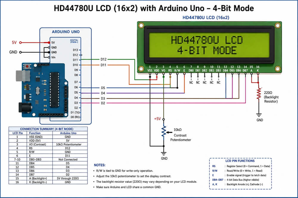
In this project, we will connect an HD44780U-compatible 16×2 LCD to an Arduino Uno and operate it in 4-bit mode.
Why Use 4-Bit Mode?An LCD in 8-bit mode requires eight data lines:
DB0–DB7
In addition, the controller needs:
- RS
- R/W
- E
That means the interface can consume a significant number of MCU GPIO pins.
In 4-bit mode, only:
- DB4
- DB5
- DB6
- DB7
are used for data.
Together with:
- RS
- E
the Arduino needs only six digital output pins when R/W is permanently tied to ground.
This is also the basic configuration used by the Arduino LiquidCrystal library examples.
Understanding the LCD PinsA typical 16-pin HD44780-compatible LCD module uses the following interface:
Pin 1: VSS -- Ground
Pin 2: VDD -- Supply voltage
Pin 3: VO -- Contrast voltage
Pin 4: RS -- Register Select
Pin 5: R/W -- Read/Write
Pin 6: E -- Enable
Pin 7: DB0 -- Data bit 0
Pin 8: DB1 -- Data bit 1
Pin 9: DB2 -- Data bit 2
Pin 10: DB3 -- Data bit 3
Pin 11: DB4 -- Data bit 4
Pin 12: DB5 -- Data bit 5
Pin 13: DB6 -- Data bit 6
Pin 14: DB7 -- Data bit 7
Pin 15: A -- Backlight anode*
Pin 16: K -- Backlight cathode*
* Backlight implementation varies between LCD modules, so check the module datasheet before applying power.
In 4-bit mode, DB0–DB3 are not connected.


Comments