


Hardware components | ||||||
 |
| × | 1 | |||
Software apps and online services | ||||||
| ||||||
This is a simple project that demonstrates how to connect your device to a system that immediately provides functionality where you can monitor the status and issue commands to turn the on board LED on/off from your phone.
The NodeMCU board is running a web server that connects to your local WiFi network. The role of the OnSiteMonitor (OSM) system is to scan your device every few seconds and report the status. When your phone is logged into your OSM account, you can see the current status of your NodeMCU board and issue commands to turn the LED light on or off. Processed commands will update the status on your OSM console running on your computer.
Overview of Steps1. You will download and install OnSiteMonitor.
2. Create your DIY device. This will provide the parameters needed for your NodeMCU board to communicate with OSM.
3. Add your device to OSM for monitoring and control.
4. Download the the Arduino Sketch on your board. In the editor, update the OSM parameters.
5. Upload and test the sketch on your NodeMCU board.
OnSiteMonitor
Adding the device to your OnSiteMonitor Console, you will be able to start sending device status and receiving action commands.
1. Download and install OnSiteMonitor v2.2 or higher
(www.OnSiteMonitor.com/download.aspx). You will be prompted for information to create your account.
2. Add your NodeMCU to OnSiteMonitor
3. Select the "DIY" tab.
- Enter "BlinkyLED" as the "Device Name".
- Enter "BlinkyLED" as the "Device ID".
- Select "NodeMCU" as the "Device Type".
- Enter "BlinkyLED" as the "Node Name".
- Select "On/Off" as the "Command Set".
- Click the "Create" button to create your new device.
4. Select the ‘Setup’ tab in OnSiteMonitor.
5. Click the ‘Add/Remove Devices button.
6. Select the ‘Add A New Device’ option
- Select ‘NodeMCU’ for the Manufacturer option.
- Select ‘BlinkyLED’ for the Model.
- Enter a custom Device Name.
- Enter a Location.
- Enter a Category.
- Select ‘Yes’ for Allows Remote Access.
- Click the ‘Add’ button to add the device to OnSiteMonitor.
7. Click ‘OK’ when the device has been added.
8. Select the ‘Dashboard’ tab.
9. The new device will be displayed in the list of devices.
NodeMCU
Arduino Sketch: Download the sketch from this project.
In the Arduino Editor:
- Select the correct board (Tools menu option)
- Select the correct Port (Tools menu option)
Sketch Parameters: Back in your OSM console, select the DIY tab, then select your DIY device. This will display the parameters needed for your sketch:
- Account Id
- Device ID
- Device Type
- Command Class
These parameters can be found by logging into your web account and selecting your DIY device.
WiFi Access:
- Update the "ssid" parameter with your router ID for WiFi access.
- Update the "password" parameter with the password for your router/SSID.
- These parameters are case sensitive!
Serial Monitor: The following is the sample output from the Arduino IDE Serial Monitor tool. Per the code, it will first connect to your WiFi network, display the IP Address of the device.
Once the parameters have been updated, upload the sketch to your NodeMCU board. Verify that your device connects to WiFi and obtains an IP Address:
When you upload the sketch, you should get two IP Addresses similar to the above example. If you do not, you cannot proceed until you do.
Back To OnSiteMonitor1. Stop and restart the OnSiteMonitor console.
2. Once the device starts to scan, the status will appear below the device name.
3. To issue a control to the device, click the ‘BlinkyLED’ button.
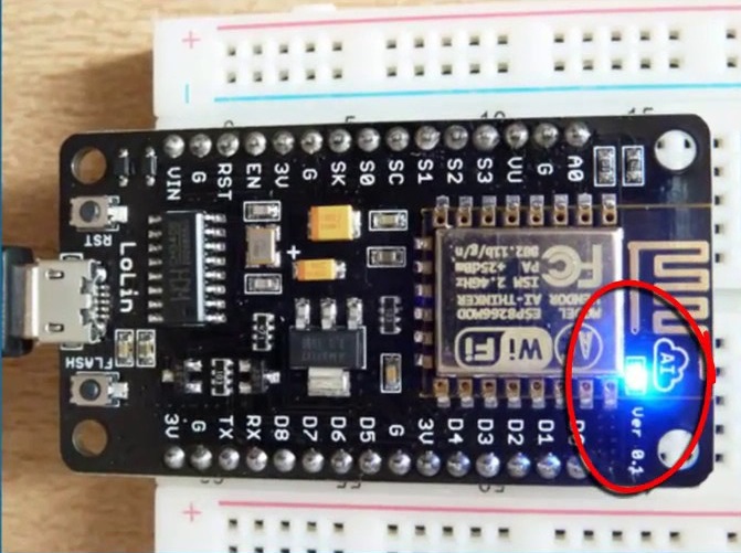
7. To turn the on board LED off, click the ‘Off’button. Watch the light on the NodeMCU turn off.
8. To turn the on board LED on, click the ‘On’button. Watch the light on the NodeMCU turn on..
9. Click the ‘Close’ button to return to the dashboard.
10. The status of the device should change at the device has been scanned.
11. If you log into your www.OnSiteMonitor.com web account, your new device will be displayed where you can see the device status and issue controls remotely.


Comments