

Hardware components | ||||||
 |
| × | 1 | |||
| × | 1 | ||||
| × | 1 | ||||
| × | 1 | ||||
| × | 1 | ||||
Project:
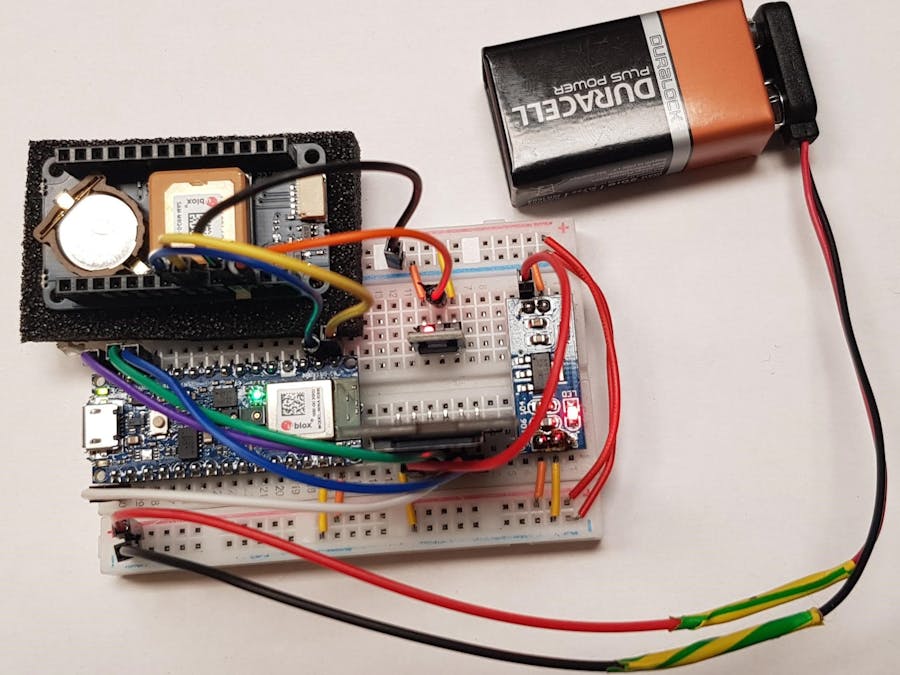
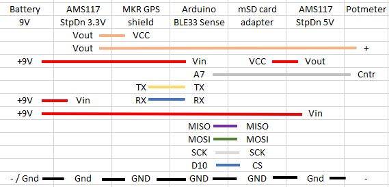
Read moreGPS and AHRS data logger on SD card. Connecting Arduino Nano 33 BLE Sense, MKR GPS Shield with ublox 8M GPS and mSD card adapter.
Connect the datalogger to a 9V battery and a data file will be written to the mSD card.
The 3 color LED on the Arduino shows the status of the logger:
- red: initializing,
- blue: initialized and waiting to find satellites,
- green: satellites find and logging data to the card.
Resulting file on the SD card:
more information o the data from the GPS can be found here.
This logger is used to capture data from an RC boat. The SDC on A7 is used to read a potmeter which tells the height above the water.
Note the data includes Pitch, Roll and Yaw (last three columns).
/****************************************************************************
 * Data Logger v30
 * 28-Jan-21
 * Ruud Kapteijn
 * Available under GPL3+
 *
 * Uses the AHRS Madgwick code from Kris Winer (ref AHRS.h)
 * Original code by Kris Winer
 * date: Nov 1, 2014
 * code: https://github.com/j-mcc1993/LSM9DS1/blob/master/LSM9DS1_BasicAHRS_Nano33.ino
 * discussion threa: https://github.com/kriswiner/LSM9DS1/issues/14
 */
#include <Arduino_LSM9DS1.h>
#include <Arduino_LPS22HB.h> //Include library to read Pressure
#include <SPI.h>
#include <SD.h>
// #include <RF24.h>

#include "Ublox_NMEA_GPS.h"
#include "AHRS.h"
#include "AHRS_gvars.h"

#define LEDR        (22u)
#define LEDG        (23u)
#define LEDB        (24u)
#define LEDPWR      (25u)

// GPS Vars
Ublox_NMEA_GPS myGPS;
boolean fix = false;
int satellites, prev_satellites;

// potentionmeter
int potmeter = 0;

// IMU Vars
// float ax, ay, az;
// float gx, gy, gz;
// float mx, my, mz;

// Baro vars
float pressure;

// SD Vars
File dataFile;
int chipSelect = 10;
int seqnr = 0;
String fileName;
int counter = 0;
int byteCounter = 0;
String dataString;
long last_write = 0;

/*
// transmitter vars
RF24 radio(9, 10); // CE, CSN
const byte address[6] = "00001";     //Byte of array representing the address. This is the address where we will send the data. This should be same on the receiving side.
long last_write = 0;
char tx_buffer[256];
String dataString;
int counter = 0;
int stringLength = 0;
const char ping[] = "ping";
*/

// statistic vars
boolean first_fix = true;
long    start_loops;
long    count_loops=0;
long    count_RMC = 0;
long    count_GGA = 0;

void setup() {                                    // switch buildin LED off
  digitalWrite(LEDPWR, HIGH); digitalWrite(LEDR, HIGH); digitalWrite(LEDG, HIGH);  digitalWrite(LEDB, HIGH);
  digitalWrite(LEDR, LOW);                        // switch buildin LED to red -> not initialized.

  Serial.begin(9600);                             // Open serial communications and wait for port to open:
  // while (!Serial);                                // wait until monitor is opened
  Serial.println("INFO: ** Telemetry V10 **");

  myGPS.init();
  Serial.println("INFO: GPS Started");

  if (!IMU.begin()) {
    Serial.println("ERROR: Failed to initialize IMU! halted.");
    while (true);
  }
  Serial.println("INFO: IMU Started!");

  if (!BARO.begin()) {        //Initialize Pressure sensor
    Serial.println("ERROR: Failed to initialize Pressure Sensor! halted.");
    while (1);
  }
  Serial.println("INFO: BARO Started!");

  if (AHRS_setup())
    Serial.println("INFO: AHRS setup ok");
  else {
    Serial.println("ERROR AHRS setup failed. Halted!");
    while(true);
  }

/*
  radio.begin();                  //Starting the Wireless communication
  radio.openWritingPipe(address); //Setting the address where we will send the data
  radio.setPALevel(RF24_PA_MIN);  //You can set it as minimum or maximum depending on the distance between the transmitter and receiver.
  radio.stopListening();          //This sets the module as transmitter
  Serial.println("INFO: Transmitter started");
*/

  if (!SD.begin(chipSelect)) {              // Setup SD Card
   Serial.println("ERROR: SD Card failed or not present! Halted.");
   while (1);
  }
  Serial.println("INFO: SD card initialized");
  seqnr = 1;                              // Check on existing files
  fileName = "DL" + String(seqnr) + ".CSV";
  while(SD.exists(fileName)) {
    seqnr++;
    fileName = "DL" + String(seqnr) + ".CSV";
    delay(200); // Make sure file access is done
  }
  dataFile = SD.open(fileName, FILE_WRITE);   // Create new CSV file with appropriate headers
  dataFile.println("Nr,Mills,Date,UTC,Lat,Lon,Sog,Cog,Alt,Sat,Fix,Pm,Ax,Ay,Az,Gx,Gy,Gz,Mx,My,Mz,Pres,Pitch,Roll,Yaw");
  Serial.println("INFO: new data file created, ready for logging.");      // Done with SD Card Init

  digitalWrite(LEDR, HIGH);                       // switch buildin LED off
  digitalWrite(LEDB, LOW);                        // switch buildin LED to blue -> looking for satellites.
  Serial.println("Initialization completed");
}

void loop() {                                     // run continuously
  myGPS.update();
  prev_satellites = satellites;
  satellites = myGPS.getSIV().toInt();
  if (satellites != prev_satellites)
    Serial.println("SIV: " + String(satellites) + " Pitch: " + String(pitch));

  if (satellites > 2) {                          // return TRUE if fix
    if (!fix) Serial.println("INFO: Fix created!");
    fix = true;
    digitalWrite(LEDB, HIGH);                       // switch buildin LED off
    digitalWrite(LEDG, LOW);                        // switch buildin LED to green -> (potential) fix.
    if (first_fix) {
      first_fix = false;
      start_loops = millis();
      count_loops = 0;
      count_RMC = 0;
      count_GGA = 0;
    }
  } else {
    if (fix) Serial.println("INFO: Fix lost!");
    fix = false;
    digitalWrite(LEDG, HIGH);                       // switch buildin LED off
    digitalWrite(LEDB, LOW);                        // switch buildin LED to blue -> looking for satellites.
  }

  potmeter = analogRead(7);                           // read value of potential meter via ADC pin 7
  getIMUData();
  pressure = BARO.readPressure();

  AHRS_update();

  // write line to datafile
  if (dataFile && fix && millis() - last_write > 150) {
    counter += 1;
    dataString = createDataString();
    // dataString = "dit is een lange test data string met een hele boel bytes";
    // Serial.print("INFO: write to SD card: ");
    // Serial.println(dataString);
    dataFile.println(dataString);
    byteCounter += dataString.length();
    if (byteCounter > 1024) {
      // Serial.println("INFO: flush buffer to SD card");
      dataFile.flush();
      byteCounter = 0;
    }
  }

/*
  if (fix && millis() - last_write > 250) {     // send data string
    last_write = millis();
    counter += 1;
    dataString = createDataString() + '\n';
    // Serial.print("INFO: write to SD card: ");
    for (int i = 0; i < dataString.length(); i+=32) {
      String section = dataString.substring(i, i + 32);
      section.toCharArray(tx_buffer, sizeof(tx_buffer));
      radio.write(&tx_buffer, section.length());           //Sending the message to receiver
    }
  }
*/

  count_loops++;
  if (count_loops % 1000 == 0) {
    Serial.println("loops: "+String(count_loops)+", satellites: "+myGPS.getSIV()+", pitch: "+String(pitch));
  }
  if (count_loops % 10000 ==0) {
    Serial.println("loops: "+String(count_loops)+", avg loop: "+String((millis() - start_loops)/count_loops)+" ms, avg RMC: "+String((millis() - start_loops)/count_RMC)+" ms, avg GGA: "+String((millis() - start_loops)/count_GGA));
    // radio.write(&ping, sizeof(ping));               //Sending the message to receiver
  }
}

boolean getIMUData() {
  //Accelerometer values
  if (IMU.accelerationAvailable()) {
    IMU.readAcceleration(ax, ay, az);
  }
  //Gyroscope values
  if (IMU.gyroscopeAvailable()) {
    IMU.readGyroscope(gx, gy, gz);
  }
  //Magnetometer values
  if (IMU.magneticFieldAvailable()) {
    IMU.readMagneticField(mx, my, mz);
  }
}

String createDataString() {
  String ds = "";

  ds += String(counter) + ",";
  ds += String(millis()) + ",";
  ds += myGPS.getDAT() + ",";
  ds += myGPS.getTIM() + ",";
  ds += myGPS.getLAT() + ",";
  ds += myGPS.getLON() + ",";
  ds += myGPS.getSOG() + ",";
  ds += myGPS.getCOG() + ",";
  ds += myGPS.getALT() + ",";
  ds += myGPS.getSIV() + ",";
  ds += myGPS.getFIX() + ",";

  ds += String(potmeter) + ",";

  ds += String(ax) + ",";
  ds += String(ay) + ",";
  ds += String(az) + ",";
  ds += String(gx) + ",";
  ds += String(gy) + ",";
  ds += String(gz) + ",";
  ds += String(mx) + ",";
  ds += String(my) + ",";
  ds += String(mz) + ",";

  ds += String(pressure) + ",";

  ds += String(pitch) + ",";
  ds += String(roll) + ",";
  ds += String(yaw);

  return(ds);
}
/* LSM9DS1_MS5611_t3 Basic Example Code
by: Kris Winer
date: November 1, 2014
license: Beerware - Use this code however you'd like. If you
find it useful you can buy me a beer some time.
Demonstrate basic LSM9DS1 functionality including parameterizing the register addresses, initializing the sensor,
getting properly scaled accelerometer, gyroscope, and magnetometer data out. Added display functions to
allow display to on breadboard monitor. Addition of 9 DoF sensor fusion using open source Madgwick and
Mahony filter algorithms. Sketch runs on the 3.3 V 8 MHz Pro Mini and the Teensy 3.1.
This sketch is intended specifically for the LSM9DS1+MS5611 Add-on shield for the Teensy 3.1.
It uses SDA/SCL on pins 17/16, respectively, and it uses the Teensy 3.1-specific Wire library i2c_t3.h.
The MS5611 is a simple but high resolution pressure sensor, which can be used in its high resolution
mode but with power consumption od 20 microAmp, or in a lower resolution mode with power consumption of
only 1 microAmp. The choice will depend on the application.
SDA and SCL should have external pull-up resistors (to 3.3V).
4K7 resistors are on the LSM9DS1+MS5611 Teensy 3.1 add-on shield/breakout board.
Hardware setup:
LSM9DS1Breakout --------- Arduino
VDD ---------------------- 3.3V
VDDI --------------------- 3.3V
SDA ----------------------- A4
SCL ----------------------- A5
GND ---------------------- GND
Note: The LSM9DS1 is an I2C sensor and can use the Arduino Wire library.
Because the sensor is not 5V tolerant, we are using either a 3.3 V 8 MHz Pro Mini or a 3.3 V Teensy 3.1.
We have disabled the internal pull-ups used by the Wire library in the Wire.h/twi.c utility file.
We are also using the 400 kHz fast I2C mode by setting the TWI_FREQ  to 400000L /twi.h utility file.

Modified by Ruud Kapteijn
16-Jan-2021
Moulded into class AHRS
taken out NOKIA 5110 monochrome display code
code: https://github.com/j-mcc1993/LSM9DS1/blob/master/LSM9DS1_BasicAHRS_Nano33.ino
discussion threa: https://github.com/kriswiner/LSM9DS1/issues/14
 */

// See MS5611-02BA03 Low Voltage Barometric Pressure Sensor Data Sheet
#define MS5611_RESET      0x1E
#define MS5611_CONVERT_D1 0x40
#define MS5611_CONVERT_D2 0x50
#define MS5611_ADC_READ   0x00

// See also LSM9DS1 Register Map and Descriptions, http://www.st.com/st-web-ui/static/active/en/resource/technical/document/datasheet/DM00103319.pdf
// Accelerometer and Gyroscope registers
#define LSM9DS1XG_ACT_THS      0x04
#define LSM9DS1XG_ACT_DUR     0x05
#define LSM9DS1XG_INT_GEN_CFG_XL    0x06
#define LSM9DS1XG_INT_GEN_THS_X_XL  0x07
#define LSM9DS1XG_INT_GEN_THS_Y_XL  0x08
#define LSM9DS1XG_INT_GEN_THS_Z_XL  0x09
#define LSM9DS1XG_INT_GEN_DUR_XL    0x0A
#define LSM9DS1XG_REFERENCE_G       0x0B
#define LSM9DS1XG_INT1_CTRL         0x0C
#define LSM9DS1XG_INT2_CTRL         0x0D
#define LSM9DS1XG_WHO_AM_I          0x0F  // should return 0x68
#define LSM9DS1XG_CTRL_REG1_G       0x10
#define LSM9DS1XG_CTRL_REG2_G       0x11
#define LSM9DS1XG_CTRL_REG3_G       0x12
#define LSM9DS1XG_ORIENT_CFG_G      0x13
#define LSM9DS1XG_INT_GEN_SRC_G     0x14
#define LSM9DS1XG_OUT_TEMP_L        0x15
#define LSM9DS1XG_OUT_TEMP_H        0x16
#define LSM9DS1XG_STATUS_REG        0x17
#define LSM9DS1XG_OUT_X_L_G         0x18
#define LSM9DS1XG_OUT_X_H_G         0x19
#define LSM9DS1XG_OUT_Y_L_G         0x1A
#define LSM9DS1XG_OUT_Y_H_G         0x1B
#define LSM9DS1XG_OUT_Z_L_G         0x1C
#define LSM9DS1XG_OUT_Z_H_G         0x1D
#define LSM9DS1XG_CTRL_REG4         0x1E
#define LSM9DS1XG_CTRL_REG5_XL      0x1F
#define LSM9DS1XG_CTRL_REG6_XL      0x20
#define LSM9DS1XG_CTRL_REG7_XL      0x21
#define LSM9DS1XG_CTRL_REG8         0x22
#define LSM9DS1XG_CTRL_REG9         0x23
#define LSM9DS1XG_CTRL_REG10        0x24
#define LSM9DS1XG_INT_GEN_SRC_XL    0x26
//#define LSM9DS1XG_STATUS_REG        0x27 // duplicate of 0x17!
#define LSM9DS1XG_OUT_X_L_XL        0x28
#define LSM9DS1XG_OUT_X_H_XL        0x29
#define LSM9DS1XG_OUT_Y_L_XL        0x2A
#define LSM9DS1XG_OUT_Y_H_XL        0x2B
#define LSM9DS1XG_OUT_Z_L_XL        0x2C
#define LSM9DS1XG_OUT_Z_H_XL        0x2D
#define LSM9DS1XG_FIFO_CTRL         0x2E
#define LSM9DS1XG_FIFO_SRC          0x2F
#define LSM9DS1XG_INT_GEN_CFG_G     0x30
#define LSM9DS1XG_INT_GEN_THS_XH_G  0x31
#define LSM9DS1XG_INT_GEN_THS_XL_G  0x32
#define LSM9DS1XG_INT_GEN_THS_YH_G  0x33
#define LSM9DS1XG_INT_GEN_THS_YL_G  0x34
#define LSM9DS1XG_INT_GEN_THS_ZH_G  0x35
#define LSM9DS1XG_INT_GEN_THS_ZL_G  0x36
#define LSM9DS1XG_INT_GEN_DUR_G     0x37
//
// Magnetometer registers
#define LSM9DS1M_OFFSET_X_REG_L_M   0x05
#define LSM9DS1M_OFFSET_X_REG_H_M   0x06
#define LSM9DS1M_OFFSET_Y_REG_L_M   0x07
#define LSM9DS1M_OFFSET_Y_REG_H_M   0x08
#define LSM9DS1M_OFFSET_Z_REG_L_M   0x09
#define LSM9DS1M_OFFSET_Z_REG_H_M   0x0A
#define LSM9DS1M_WHO_AM_I           0x0F  // should be 0x3D
#define LSM9DS1M_CTRL_REG1_M        0x20
#define LSM9DS1M_CTRL_REG2_M        0x21
#define LSM9DS1M_CTRL_REG3_M        0x22
#define LSM9DS1M_CTRL_REG4_M        0x23
#define LSM9DS1M_CTRL_REG5_M        0x24
#define LSM9DS1M_STATUS_REG_M       0x27
#define LSM9DS1M_OUT_X_L_M          0x28
#define LSM9DS1M_OUT_X_H_M          0x29
#define LSM9DS1M_OUT_Y_L_M          0x2A
#define LSM9DS1M_OUT_Y_H_M          0x2B
#define LSM9DS1M_OUT_Z_L_M          0x2C
#define LSM9DS1M_OUT_Z_H_M          0x2D
#define LSM9DS1M_INT_CFG_M          0x30
#define LSM9DS1M_INT_SRC_M          0x31
#define LSM9DS1M_INT_THS_L_M        0x32
#define LSM9DS1M_INT_THS_H_M        0x33

// Using the LSM9DS1+MS5611 Teensy 3.1 Add-On shield, ADO is set to 1
// Seven-bit device address of accel/gyro is 110101 for ADO = 0 and 110101 for ADO = 1
#define ADO 1
#if ADO
#define LSM9DS1XG_ADDRESS 0x6B  //  Device address when ADO = 1
#define LSM9DS1M_ADDRESS  0x1E  //  Address of magnetometer
#define MS5611_ADDRESS    0x77  //  Address of altimeter
#else
#define LSM9DS1XG_ADDRESS 0x6A   //  Device address when ADO = 0
#define LSM9DS1M_ADDRESS  0x1D   //  Address of magnetometer
#define MS5611_ADDRESS    0x77   //  Address of altimeter
#endif

#define SerialDebug true  // set to true to get Serial output for debugging

// Set initial input parameters
enum Ascale {  // set of allowable accel full scale settings
  AFS_2G = 0,
  AFS_16G,
  AFS_4G,
  AFS_8G
};

enum Aodr {  // set of allowable gyro sample rates
  AODR_PowerDown = 0,
  AODR_10Hz,
  AODR_50Hz,
  AODR_119Hz,
  AODR_238Hz,
  AODR_476Hz,
  AODR_952Hz
};

enum Abw {  // set of allowable accewl bandwidths
  ABW_408Hz = 0,
  ABW_211Hz,
  ABW_105Hz,
  ABW_50Hz
};

enum Gscale {  // set of allowable gyro full scale settings
  GFS_245DPS = 0,
  GFS_500DPS,
  GFS_NoOp,
  GFS_2000DPS
};

enum Godr {  // set of allowable gyro sample rates
  GODR_PowerDown = 0,
  GODR_14_9Hz,
  GODR_59_5Hz,
  GODR_119Hz,
  GODR_238Hz,
  GODR_476Hz,
  GODR_952Hz
};

enum Gbw {   // set of allowable gyro data bandwidths
  GBW_low = 0,  // 14 Hz at Godr = 238 Hz,  33 Hz at Godr = 952 Hz
  GBW_med,      // 29 Hz at Godr = 238 Hz,  40 Hz at Godr = 952 Hz
  GBW_high,     // 63 Hz at Godr = 238 Hz,  58 Hz at Godr = 952 Hz
  GBW_highest   // 78 Hz at Godr = 238 Hz, 100 Hz at Godr = 952 Hz
};

enum Mscale {  // set of allowable mag full scale settings
  MFS_4G = 0,
  MFS_8G,
  MFS_12G,
  MFS_16G
};

enum Mmode {
  MMode_LowPower = 0,
  MMode_MedPerformance,
  MMode_HighPerformance,
  MMode_UltraHighPerformance
};

enum Modr {  // set of allowable mag sample rates
  MODR_0_625Hz = 0,
  MODR_1_25Hz,
  MODR_2_5Hz,
  MODR_5Hz,
  MODR_10Hz,
  MODR_20Hz,
  MODR_80Hz
};

#define ADC_256  0x00 // define pressure and temperature conversion rates
#define ADC_512  0x02
#define ADC_1024 0x04
#define ADC_2048 0x06
#define ADC_4096 0x08
#define ADC_D1   0x40
#define ADC_D2   0x50

// Specify sensor full scale
extern uint8_t OSR;       // set pressure amd temperature oversample rate
extern uint8_t Gscale;    // gyro full scale
extern uint8_t Godr;      // gyro data sample rate
extern uint8_t Gbw;       // gyro data bandwidth
extern uint8_t Ascale;    // accel full scale
extern uint8_t Aodr;      // accel data sample rate
extern uint8_t Abw;       // accel data bandwidth
extern uint8_t Mscale;    // mag full scale
extern uint8_t Modr;      // mag data sample rate
extern uint8_t Mmode;     // magnetometer operation mode
extern float aRes, gRes, mRes;      // scale resolutions per LSB for the sensors

// Pin definitions
extern int myLed;

extern uint16_t Pcal[8];         // calibration constants from MS5611 PROM registers
extern unsigned char nCRC;       // calculated check sum to ensure PROM integrity
//-(rk) uint32_t D1 = 0, D2 = 0;  // raw MS5611 pressure and temperature data
extern double dT, OFFSET, SENS, T2, OFFSET2, SENS2;  // First order and second order corrections for raw S5637 temperature and pressure data
extern int16_t accelCount[3], gyroCount[3], magCount[3];  // Stores the 16-bit signed accelerometer, gyro, and mag sensor output
extern float gyroBias[3], accelBias[3], magBias[3]; // Bias corrections for gyro, accelerometer, and magnetometer
extern int16_t tempCount;            // temperature raw count output
extern float   temperature;          // Stores the LSM9DS1gyro internal chip temperature in degrees Celsius
extern double Temperature, Pressure; // stores MS5611 pressures sensor pressure and temperature

// global constants for 9 DoF fusion and AHRS (Attitude and Heading Reference System)
extern float GyroMeasError;   // gyroscope measurement error in rads/s (start at 40 deg/s)
extern float GyroMeasDrift;   // gyroscope measurement drift in rad/s/s (start at 0.0 deg/s/s)
// There is a tradeoff in the beta parameter between accuracy and response speed.
// In the original Madgwick study, beta of 0.041 (corresponding to GyroMeasError of 2.7 degrees/s) was found to give optimal accuracy.
// However, with this value, the LSM9SD0 response time is about 10 seconds to a stable initial quaternion.
// Subsequent changes also require a longish lag time to a stable output, not fast enough for a quadcopter or robot car!
// By increasing beta (GyroMeasError) by about a factor of fifteen, the response time constant is reduced to ~2 sec
// I haven't noticed any reduction in solution accuracy. This is essentially the I coefficient in a PID control sense;
// the bigger the feedback coefficient, the faster the solution converges, usually at the expense of accuracy.
// In any case, this is the free parameter in the Madgwick filtering and fusion scheme.
extern float beta;   // compute beta
extern float zeta;   // compute zeta, the other free parameter in the Madgwick scheme usually set to a small or zero value
#define Kp 2.0f * 5.0f // these are the free parameters in the Mahony filter and fusion scheme, Kp for proportional feedback, Ki for integral
#define Ki 0.0f

extern uint32_t delt_t, count, sumCount;  // used to control display output rate
extern float pitch, yaw, roll;
extern float deltat, sum;     // integration interval for both filter schemes
extern uint32_t lastUpdate, firstUpdate; // used to calculate integration interval
extern uint32_t Now;          // used to calculate integration interval

extern float ax, ay, az, gx, gy, gz, mx, my, mz; // variables to hold latest sensor data values
extern float q[4];            // vector to hold quaternion
extern float eInt[3];         // vector to hold integral error for Mahony method

//-(rk) Prototypes of AHRS.cpp
void getMres();
void getGres();
void getAres();
void readAccelData(int16_t * destination);
void readGyroData(int16_t * destination);
void readMagData(int16_t * destination);
int16_t readTempData();
void initLSM9DS1();
void selftestLSM9DS1();
void accelgyrocalLSM9DS1(float * dest1, float * dest2);
void magcalLSM9DS1(float * dest1);
void writeByte(uint8_t address, uint8_t subAddress, uint8_t data);
uint8_t readByte(uint8_t address, uint8_t subAddress);
void readBytes(uint8_t address, uint8_t subAddress, uint8_t count, uint8_t * dest);
void MadgwickQuaternionUpdate(float ax, float ay, float az, float gx, float gy, float gz, float mx, float my, float mz);

boolean AHRS_setup();
void AHRS_update();
/* LSM9DS1_MS5611_t3 Basic Example Code
by: Kris Winer
date: November 1, 2014
license: Beerware - Use this code however you'd like. If you
find it useful you can buy me a beer some time.
Demonstrate basic LSM9DS1 functionality including parameterizing the register addresses, initializing the sensor,
getting properly scaled accelerometer, gyroscope, and magnetometer data out. Added display functions to
allow display to on breadboard monitor. Addition of 9 DoF sensor fusion using open source Madgwick and
Mahony filter algorithms. Sketch runs on the 3.3 V 8 MHz Pro Mini and the Teensy 3.1.
This sketch is intended specifically for the LSM9DS1+MS5611 Add-on shield for the Teensy 3.1.
It uses SDA/SCL on pins 17/16, respectively, and it uses the Teensy 3.1-specific Wire library i2c_t3.h.
The MS5611 is a simple but high resolution pressure sensor, which can be used in its high resolution
mode but with power consumption od 20 microAmp, or in a lower resolution mode with power consumption of
only 1 microAmp. The choice will depend on the application.
SDA and SCL should have external pull-up resistors (to 3.3V).
4K7 resistors are on the LSM9DS1+MS5611 Teensy 3.1 add-on shield/breakout board.
Hardware setup:
LSM9DS1Breakout --------- Arduino
VDD ---------------------- 3.3V
VDDI --------------------- 3.3V
SDA ----------------------- A4
SCL ----------------------- A5
GND ---------------------- GND
Note: The LSM9DS1 is an I2C sensor and can use the Arduino Wire library.
Because the sensor is not 5V tolerant, we are using either a 3.3 V 8 MHz Pro Mini or a 3.3 V Teensy 3.1.
We have disabled the internal pull-ups used by the Wire library in the Wire.h/twi.c utility file.
We are also using the 400 kHz fast I2C mode by setting the TWI_FREQ  to 400000L /twi.h utility file.

Modified by Ruud Kapteijn
16-Jan-2021
Moulded into class AHRS
taken out NOKIA 5110 monochrome display code
code: https://github.com/j-mcc1993/LSM9DS1/blob/master/LSM9DS1_BasicAHRS_Nano33.ino
discussion threa: https://github.com/kriswiner/LSM9DS1/issues/14
 */
#include <Arduino.h>
#include <Arduino_LSM9DS1.h>
#include <Arduino_LPS22HB.h> //Include library to read Pressure
#include <Wire.h>
#include <SPI.h>
#include "AHRS.h"

boolean AHRS_setup() {
  Wire1.begin();
  //  TWBR = 12;  // 400 kbit/sec I2C speed for Pro Mini
  // Setup for Master mode, pins 16/17, external pullups, 400kHz for Teensy 3.1
  //Wire.begin(I2C_MASTER, 0x00, I2C_PINS_16_17, I2C_PULLUP_EXT, I2C_RATE_400);
  // reset
  writeByte(LSM9DS1XG_ADDRESS, LSM9DS1XG_CTRL_REG8, 0x05);
  writeByte(LSM9DS1M_ADDRESS, LSM9DS1M_CTRL_REG2_M, 0x0c);
  delay(100);

  // Initialize LED pin
  pinMode(myLed, OUTPUT);
  digitalWrite(myLed, HIGH);

  // Read the WHO_AM_I registers, this is a good test of communication
  Serial.println("LSM9DS1 9-axis motion sensor...");
  byte c = readByte(LSM9DS1XG_ADDRESS, LSM9DS1XG_WHO_AM_I);  // Read WHO_AM_I register for LSM9DS1 accel/gyro
  Serial.print("LSM9DS1 accel/gyro"); Serial.print("I AM "); Serial.print(c, HEX); Serial.print(" I should be "); Serial.println(0x68, HEX);
  byte d = readByte(LSM9DS1M_ADDRESS, LSM9DS1M_WHO_AM_I);  // Read WHO_AM_I register for LSM9DS1 magnetometer
  Serial.print("LSM9DS1 magnetometer"); Serial.print("I AM "); Serial.print(d, HEX); Serial.print(" I should be "); Serial.println(0x3D, HEX);

  if (c == 0x68 && d == 0x3D) // WHO_AM_I should always be 0x0E for the accel/gyro and 0x3C for the mag
  {
    Serial.println("LSM9DS1 is online...");

    // get sensor resolutions, only need to do this once
    getAres();
    getGres();
    getMres();
    Serial.print("accel sensitivity is "); Serial.print(1./(1000.*aRes)); Serial.println(" LSB/mg");
    Serial.print("gyro sensitivity is "); Serial.print(1./(1000.*gRes)); Serial.println(" LSB/mdps");
    Serial.print("mag sensitivity is "); Serial.print(1./(1000.*mRes)); Serial.println(" LSB/mGauss");

    Serial.println("Perform gyro and accel self test");
    selftestLSM9DS1(); // check function of gyro and accelerometer via self test

    Serial.println(" Calibrate gyro and accel");
    accelgyrocalLSM9DS1(gyroBias, accelBias); // Calibrate gyro and accelerometers, load biases in bias registers
    Serial.println("accel biases (mg)"); Serial.println(1000.*accelBias[0]); Serial.println(1000.*accelBias[1]); Serial.println(1000.*accelBias[2]);
    Serial.println("gyro biases (dps)"); Serial.println(gyroBias[0]); Serial.println(gyroBias[1]); Serial.println(gyroBias[2]);

    magcalLSM9DS1(magBias);
    Serial.println("mag biases (mG)"); Serial.println(1000.*magBias[0]); Serial.println(1000.*magBias[1]); Serial.println(1000.*magBias[2]);
    delay(2000); // add delay to see results before serial spew of data

    initLSM9DS1();
    Serial.println("LSM9DS1 initialized for active data mode...."); // Initialize device for active mode read of acclerometer, gyroscope, and temperature
    return true;
  }
  else
  {
    Serial.print("Could not connect to LSM9DS1: 0x");
    Serial.println(c, HEX);
    return false;
  }
}

void AHRS_update() {
  int DEBUG = 0;

    if (readByte(LSM9DS1XG_ADDRESS, LSM9DS1XG_STATUS_REG) & 0x01) {  // check if new accel data is ready
      readAccelData(accelCount);  // Read the x/y/z adc values

      // Now we'll calculate the accleration value into actual g's
      ax = (float)accelCount[0]*aRes - accelBias[0];  // get actual g value, this depends on scale being set
      ay = (float)accelCount[1]*aRes - accelBias[1];
      az = (float)accelCount[2]*aRes - accelBias[2];
    }

    if (readByte(LSM9DS1XG_ADDRESS, LSM9DS1XG_STATUS_REG) & 0x02) {  // check if new gyro data is ready
      readGyroData(gyroCount);  // Read the x/y/z adc values

      // Calculate the gyro value into actual degrees per second
      gx = (float)gyroCount[0]*gRes - gyroBias[0];  // get actual gyro value, this depends on scale being set
      gy = (float)gyroCount[1]*gRes - gyroBias[1];
      gz = (float)gyroCount[2]*gRes - gyroBias[2];
    }

    if (readByte(LSM9DS1M_ADDRESS, LSM9DS1M_STATUS_REG_M) & 0x08) {  // check if new mag data is ready
      readMagData(magCount);  // Read the x/y/z adc values

      // Calculate the magnetometer values in milliGauss
      // Include factory calibration per data sheet and user environmental corrections
      mx = (float)magCount[0]*mRes; // - magBias[0];  // get actual magnetometer value, this depends on scale being set
      my = (float)magCount[1]*mRes; // - magBias[1];
      mz = (float)magCount[2]*mRes; // - magBias[2];
    }

    Now = micros();
    deltat = ((Now - lastUpdate)/1000000.0f); // set integration time by time elapsed since last filter update
    lastUpdate = Now;

    sum += deltat; // sum for averaging filter update rate
    sumCount++;

    // Sensors x, y, and z axes of the accelerometer and gyro are aligned. The magnetometer
    // the magnetometer z-axis (+ up) is aligned with the z-axis (+ up) of accelerometer and gyro, but the magnetometer
    // x-axis is aligned with the -x axis of the gyro and the magnetometer y axis is aligned with the y axis of the gyro!
    // We have to make some allowance for this orientation mismatch in feeding the output to the quaternion filter.
    // For the LSM9DS1, we have chosen a magnetic rotation that keeps the sensor forward along the x-axis just like
    // in the LSM9DS0 sensor. This rotation can be modified to allow any convenient orientation convention.
    // This is ok by aircraft orientation standards!
    // Pass gyro rate as rad/s
    MadgwickQuaternionUpdate(ax, ay, az, gx*PI/180.0f, gy*PI/180.0f, gz*PI/180.0f, -mx, -my, mz);
    //  MahonyQuaternionUpdate(ax, ay, az, gx*PI/180.0f, gy*PI/180.0f, gz*PI/180.0f, -mx, my, mz);

    // Serial print and/or display at 0.5 s rate independent of data rates
    delt_t = millis() - count;
    if (delt_t > 500) { // update LCD once per half-second independent of read rate

      if(SerialDebug && DEBUG > 0) {
        Serial.print("lib -> ax = "); Serial.print((int)1000*ax);
        Serial.print(" ay = "); Serial.print((int)1000*ay);
        Serial.print(" az = "); Serial.print((int)1000*az); Serial.println(" mg");
        Serial.print("gx = "); Serial.print( gx, 2);
        Serial.print(" gy = "); Serial.print( gy, 2);
        Serial.print(" gz = "); Serial.print( gz, 2); Serial.println(" deg/s");
        Serial.print("mx = "); Serial.print( (int)1000*mx );
        Serial.print(" my = "); Serial.print( (int)1000*my );
        Serial.print(" mz = "); Serial.print( (int)1000*mz ); Serial.println(" mG");

        Serial.print("q0 = "); Serial.print(q[0]);
        Serial.print(" qx = "); Serial.print(q[1]);
        Serial.print(" qy = "); Serial.print(q[2]);
        Serial.print(" qz = "); Serial.println(q[3]);
      }
      tempCount = readTempData();  // Read the gyro adc values
      temperature = ((float) tempCount/256. + 25.0); // Gyro chip temperature in degrees Centigrade
      // Print temperature in degrees Centigrade
      if (SerialDebug && DEBUG > 0) {
        Serial.print("Gyro temperature is ");  Serial.print(temperature, 1);  Serial.println(" degrees C"); // Print T values to tenths of s degree C
      }

      // Define output variables from updated quaternion---these are Tait-Bryan angles, commonly used in aircraft orientation.
      // In this coordinate system, the positive z-axis is down toward Earth.
      // Yaw is the angle between Sensor x-axis and Earth magnetic North (or true North if corrected for local declination, looking down on the sensor positive yaw is counterclockwise.
      // Pitch is angle between sensor x-axis and Earth ground plane, toward the Earth is positive, up toward the sky is negative.
      // Roll is angle between sensor y-axis and Earth ground plane, y-axis up is positive roll.
      // These arise from the definition of the homogeneous rotation matrix constructed from quaternions.
      // Tait-Bryan angles as well as Euler angles are non-commutative; that is, the get the correct orientation the rotations must be
      // applied in the correct order which for this configuration is yaw, pitch, and then roll.
      // For more see http://en.wikipedia.org/wiki/Conversion_between_quaternions_and_Euler_angles which has additional links.
      yaw   = atan2(2.0f * (q[1] * q[2] + q[0] * q[3]), q[0] * q[0] + q[1] * q[1] - q[2] * q[2] - q[3] * q[3]);
      pitch = -asin(2.0f * (q[1] * q[3] - q[0] * q[2]));
      roll  = atan2(2.0f * (q[0] * q[1] + q[2] * q[3]), q[0] * q[0] - q[1] * q[1] - q[2] * q[2] + q[3] * q[3]);
      pitch *= 180.0f / PI;
      yaw   *= 180.0f / PI;
      yaw   -= 1.0f; // Declination at Amsterdam in 2021
      roll  *= 180.0f / PI;

      if(SerialDebug && DEBUG > 0) {
        Serial.print("lib -> Yaw, Pitch, Roll: ");
        Serial.print(yaw, 2);
        Serial.print(", ");
        Serial.print(pitch, 2);
        Serial.print(", ");
        Serial.println(roll, 2);
        // Serial.print("rate = "); Serial.print((float)sumCount/sum, 2); Serial.println(" Hz\n");
      }
      // With these settings the filter is updating at a ~145 Hz rate using the Madgwick scheme and
      // >200 Hz using the Mahony scheme even though the display refreshes at only 2 Hz.
      // The filter update rate is determined mostly by the mathematical steps in the respective algorithms,
      // the processor speed (8 MHz for the 3.3V Pro Mini), and the magnetometer ODR:
      // an ODR of 10 Hz for the magnetometer produce the above rates, maximum magnetometer ODR of 100 Hz produces
      // filter update rates of 36 - 145 and ~38 Hz for the Madgwick and Mahony schemes, respectively.
      // This is presumably because the magnetometer read takes longer than the gyro or accelerometer reads.
      // This filter update rate should be fast enough to maintain accurate platform orientation for
      // stabilization control of a fast-moving robot or quadcopter. Compare to the update rate of 200 Hz
      // produced by the on-board Digital Motion Processor of Invensense's MPU6050 6 DoF and MPU9150 9DoF sensors.
      // The 3.3 V 8 MHz Pro Mini is doing pretty well!

      digitalWrite(myLed, !digitalRead(myLed));
      count = millis();
      sumCount = 0;
      sum = 0;
    }
  }

//===================================================================================================================
//====== Set of useful function to access acceleration. gyroscope, magnetometer, and temperature data
//===================================================================================================================

void getMres() {
  switch (Mscale)
  {
    // Possible magnetometer scales (and their register bit settings) are:
    // 4 Gauss (00), 8 Gauss (01), 12 Gauss (10) and 16 Gauss (11)
    case MFS_4G:
      mRes = 4.0/32768.0;
      break;
    case MFS_8G:
      mRes = 8.0/32768.0;
      break;
    case MFS_12G:
      mRes = 12.0/32768.0;
      break;
    case MFS_16G:
      mRes = 16.0/32768.0;
      break;
  }
}

void getGres() {
  switch (Gscale)
  {
    // Possible gyro scales (and their register bit settings) are:
    // 245 DPS (00), 500 DPS (01), and 2000 DPS  (11).
    case GFS_245DPS:
      gRes = 245.0/32768.0;
      break;
    case GFS_500DPS:
      gRes = 500.0/32768.0;
      break;
    case GFS_2000DPS:
      gRes = 2000.0/32768.0;
      break;
  }
}

void getAres() {
  switch (Ascale)
  {
    // Possible accelerometer scales (and their register bit settings) are:
    // 2 Gs (00), 16 Gs (01), 4 Gs (10), and 8 Gs  (11).
    case AFS_2G:
      aRes = 2.0/32768.0;
      break;
    case AFS_16G:
      aRes = 16.0/32768.0;
      break;
    case AFS_4G:
      aRes = 4.0/32768.0;
      break;
    case AFS_8G:
      aRes = 8.0/32768.0;
      break;
  }
}


void readAccelData(int16_t * destination)
{
  uint8_t rawData[6];  // x/y/z accel register data stored here
  readBytes(LSM9DS1XG_ADDRESS, LSM9DS1XG_OUT_X_L_XL, 6, &rawData[0]);  // Read the six raw data registers into data array
  destination[0] = ((int16_t)rawData[1] << 8) | rawData[0] ;  // Turn the MSB and LSB into a signed 16-bit value
  destination[1] = ((int16_t)rawData[3] << 8) | rawData[2] ;
  destination[2] = ((int16_t)rawData[5] << 8) | rawData[4] ;
}


void readGyroData(int16_t * destination)
{
  uint8_t rawData[6];  // x/y/z gyro register data stored here
  readBytes(LSM9DS1XG_ADDRESS, LSM9DS1XG_OUT_X_L_G, 6, &rawData[0]);  // Read the six raw data registers sequentially into data array
  destination[0] = ((int16_t)rawData[1] << 8) | rawData[0] ;  // Turn the MSB and LSB into a signed 16-bit value
  destination[1] = ((int16_t)rawData[3] << 8) | rawData[2] ;
  destination[2] = ((int16_t)rawData[5] << 8) | rawData[4] ;
}

void readMagData(int16_t * destination)
{
  uint8_t rawData[6];  // x/y/z gyro register data stored here
  readBytes(LSM9DS1M_ADDRESS, LSM9DS1M_OUT_X_L_M, 6, &rawData[0]);  // Read the six raw data registers sequentially into data array
  destination[0] = ((int16_t)rawData[1] << 8) | rawData[0] ;  // Turn the MSB and LSB into a signed 16-bit value
  destination[1] = ((int16_t)rawData[3] << 8) | rawData[2] ;  // Data stored as little Endian
  destination[2] = ((int16_t)rawData[5] << 8) | rawData[4] ;
}

int16_t readTempData()
{
  uint8_t rawData[2];  // x/y/z gyro register data stored here
  readBytes(LSM9DS1XG_ADDRESS, LSM9DS1XG_OUT_TEMP_L, 2, &rawData[0]);  // Read the two raw data registers sequentially into data array
  return (((int16_t)rawData[1] << 8) | rawData[0]);  // Turn the MSB and LSB into a 16-bit signed value
}


void initLSM9DS1()
{
  // enable the 3-axes of the gyroscope
  writeByte(LSM9DS1XG_ADDRESS, LSM9DS1XG_CTRL_REG4, 0x38);
  // configure the gyroscope
  writeByte(LSM9DS1XG_ADDRESS, LSM9DS1XG_CTRL_REG1_G, Godr << 5 | Gscale << 3 | Gbw);
  delay(200);
  // enable the three axes of the accelerometer
  writeByte(LSM9DS1XG_ADDRESS, LSM9DS1XG_CTRL_REG5_XL, 0x38);
  // configure the accelerometer-specify bandwidth selection with Abw
  writeByte(LSM9DS1XG_ADDRESS, LSM9DS1XG_CTRL_REG6_XL, Aodr << 5 | Ascale << 3 | 0x04 |Abw);
  delay(200);
  // enable block data update, allow auto-increment during multiple byte read
  writeByte(LSM9DS1XG_ADDRESS, LSM9DS1XG_CTRL_REG8, 0x44);
  // configure the magnetometer-enable temperature compensation of mag data
  writeByte(LSM9DS1M_ADDRESS, LSM9DS1M_CTRL_REG1_M, 0x80 | Mmode << 5 | Modr << 2); // select x,y-axis mode
  writeByte(LSM9DS1M_ADDRESS, LSM9DS1M_CTRL_REG2_M, Mscale << 5 ); // select mag full scale
  writeByte(LSM9DS1M_ADDRESS, LSM9DS1M_CTRL_REG3_M, 0x00 ); // continuous conversion mode
  writeByte(LSM9DS1M_ADDRESS, LSM9DS1M_CTRL_REG4_M, Mmode << 2 ); // select z-axis mode
  writeByte(LSM9DS1M_ADDRESS, LSM9DS1M_CTRL_REG5_M, 0x40 ); // select block update mode
}


void selftestLSM9DS1()
{
  float accel_noST[3] = {0., 0., 0.}, accel_ST[3] = {0., 0., 0.};
  float gyro_noST[3] = {0., 0., 0.}, gyro_ST[3] = {0., 0., 0.};

  writeByte(LSM9DS1XG_ADDRESS, LSM9DS1XG_CTRL_REG10,   0x00); // disable self test
  accelgyrocalLSM9DS1(gyro_noST, accel_noST);
  writeByte(LSM9DS1XG_ADDRESS, LSM9DS1XG_CTRL_REG10,   0x05); // enable gyro/accel self test
  accelgyrocalLSM9DS1(gyro_ST, accel_ST);

  float gyrodx = (gyro_ST[0] - gyro_noST[0]);
  float gyrody = (gyro_ST[1] - gyro_noST[1]);
  float gyrodz = (gyro_ST[2] - gyro_noST[2]);

  Serial.println("Gyro self-test results: ");
  Serial.print("x-axis = "); Serial.print(gyrodx); Serial.print(" dps"); Serial.println(" should be between 20 and 250 dps");
  Serial.print("y-axis = "); Serial.print(gyrody); Serial.print(" dps"); Serial.println(" should be between 20 and 250 dps");
  Serial.print("z-axis = "); Serial.print(gyrodz); Serial.print(" dps"); Serial.println(" should be between 20 and 250 dps");

  float accdx = 1000.*(accel_ST[0] - accel_noST[0]);
  float accdy = 1000.*(accel_ST[1] - accel_noST[1]);
  float accdz = 1000.*(accel_ST[2] - accel_noST[2]);

  Serial.println("Accelerometer self-test results: ");
  Serial.print("x-axis = "); Serial.print(accdx); Serial.print(" mg"); Serial.println(" should be between 60 and 1700 mg");
  Serial.print("y-axis = "); Serial.print(accdy); Serial.print(" mg"); Serial.println(" should be between 60 and 1700 mg");
  Serial.print("z-axis = "); Serial.print(accdz); Serial.print(" mg"); Serial.println(" should be between 60 and 1700 mg");

  writeByte(LSM9DS1XG_ADDRESS, LSM9DS1XG_CTRL_REG10,   0x00); // disable self test
  delay(200);
}
// Function which accumulates gyro and accelerometer data after device initialization. It calculates the average
// of the at-rest readings and then loads the resulting offsets into accelerometer and gyro bias registers.
void accelgyrocalLSM9DS1(float * dest1, float * dest2)
{
  uint8_t data[6] = {0, 0, 0, 0, 0, 0};
  int32_t gyro_bias[3] = {0, 0, 0}, accel_bias[3] = {0, 0, 0};
  uint16_t samples, ii;

  // enable the 3-axes of the gyroscope
  writeByte(LSM9DS1XG_ADDRESS, LSM9DS1XG_CTRL_REG4, 0x38);
  // configure the gyroscope
  writeByte(LSM9DS1XG_ADDRESS, LSM9DS1XG_CTRL_REG1_G, Godr << 5 | Gscale << 3 | Gbw);
  delay(200);
  // enable the three axes of the accelerometer
  writeByte(LSM9DS1XG_ADDRESS, LSM9DS1XG_CTRL_REG5_XL, 0x38);
  // configure the accelerometer-specify bandwidth selection with Abw
  writeByte(LSM9DS1XG_ADDRESS, LSM9DS1XG_CTRL_REG6_XL, Aodr << 5 | Ascale << 3 | 0x04 |Abw);
  delay(200);
  // enable block data update, allow auto-increment during multiple byte read
  writeByte(LSM9DS1XG_ADDRESS, LSM9DS1XG_CTRL_REG8, 0x44);

  // First get gyro bias
  byte c = readByte(LSM9DS1XG_ADDRESS, LSM9DS1XG_CTRL_REG9);
  writeByte(LSM9DS1XG_ADDRESS, LSM9DS1XG_CTRL_REG9, c | 0x02);     // Enable gyro FIFO
  delay(50);                                                       // Wait for change to take effect
  writeByte(LSM9DS1XG_ADDRESS, LSM9DS1XG_FIFO_CTRL, 0x20 | 0x1F);  // Enable gyro FIFO stream mode and set watermark at 32 samples
  delay(1000);  // delay 1000 milliseconds to collect FIFO samples

  samples = (readByte(LSM9DS1XG_ADDRESS, LSM9DS1XG_FIFO_SRC) & 0x2F); // Read number of stored samples

  for(ii = 0; ii < samples ; ii++) {            // Read the gyro data stored in the FIFO
    int16_t gyro_temp[3] = {0, 0, 0};
    readBytes(LSM9DS1XG_ADDRESS, LSM9DS1XG_OUT_X_L_G, 6, &data[0]);
    gyro_temp[0] = (int16_t) (((int16_t)data[1] << 8) | data[0]); // Form signed 16-bit integer for each sample in FIFO
    gyro_temp[1] = (int16_t) (((int16_t)data[3] << 8) | data[2]);
    gyro_temp[2] = (int16_t) (((int16_t)data[5] << 8) | data[4]);

    gyro_bias[0] += (int32_t) gyro_temp[0]; // Sum individual signed 16-bit biases to get accumulated signed 32-bit biases
    gyro_bias[1] += (int32_t) gyro_temp[1];
    gyro_bias[2] += (int32_t) gyro_temp[2];
  }

  gyro_bias[0] /= samples; // average the data
  gyro_bias[1] /= samples;
  gyro_bias[2] /= samples;

  dest1[0] = (float)gyro_bias[0]*gRes;  // Properly scale the data to get deg/s
  dest1[1] = (float)gyro_bias[1]*gRes;
  dest1[2] = (float)gyro_bias[2]*gRes;

  c = readByte(LSM9DS1XG_ADDRESS, LSM9DS1XG_CTRL_REG9);
  writeByte(LSM9DS1XG_ADDRESS, LSM9DS1XG_CTRL_REG9, c & ~0x02);   //Disable gyro FIFO
  delay(50);
  writeByte(LSM9DS1XG_ADDRESS, LSM9DS1XG_FIFO_CTRL, 0x00);  // Enable gyro bypass mode

  // now get the accelerometer bias
  c = readByte(LSM9DS1XG_ADDRESS, LSM9DS1XG_CTRL_REG9);
  writeByte(LSM9DS1XG_ADDRESS, LSM9DS1XG_CTRL_REG9, c | 0x02);     // Enable accel FIFO
  delay(50);                                                       // Wait for change to take effect
  writeByte(LSM9DS1XG_ADDRESS, LSM9DS1XG_FIFO_CTRL, 0x20 | 0x1F);  // Enable accel FIFO stream mode and set watermark at 32 samples
  delay(1000);  // delay 1000 milliseconds to collect FIFO samples

  samples = (readByte(LSM9DS1XG_ADDRESS, LSM9DS1XG_FIFO_SRC) & 0x2F); // Read number of stored samples

  for(ii = 0; ii < samples ; ii++) {            // Read the accel data stored in the FIFO
    int16_t accel_temp[3] = {0, 0, 0};
    readBytes(LSM9DS1XG_ADDRESS, LSM9DS1XG_OUT_X_L_XL, 6, &data[0]);
    accel_temp[0] = (int16_t) (((int16_t)data[1] << 8) | data[0]); // Form signed 16-bit integer for each sample in FIFO
    accel_temp[1] = (int16_t) (((int16_t)data[3] << 8) | data[2]);
    accel_temp[2] = (int16_t) (((int16_t)data[5] << 8) | data[4]);

    accel_bias[0] += (int32_t) accel_temp[0]; // Sum individual signed 16-bit biases to get accumulated signed 32-bit biases
    accel_bias[1] += (int32_t) accel_temp[1];
    accel_bias[2] += (int32_t) accel_temp[2];
  }

  accel_bias[0] /= samples; // average the data
  accel_bias[1] /= samples;
  accel_bias[2] /= samples;

  if(accel_bias[2] > 0L) {accel_bias[2] -= (int32_t) (1.0/aRes);}  // Remove gravity from the z-axis accelerometer bias calculation
  else {accel_bias[2] += (int32_t) (1.0/aRes);}

  dest2[0] = (float)accel_bias[0]*aRes;  // Properly scale the data to get g
  dest2[1] = (float)accel_bias[1]*aRes;
  dest2[2] = (float)accel_bias[2]*aRes;

  c = readByte(LSM9DS1XG_ADDRESS, LSM9DS1XG_CTRL_REG9);
  writeByte(LSM9DS1XG_ADDRESS, LSM9DS1XG_CTRL_REG9, c & ~0x02);   //Disable accel FIFO
  delay(50);
  writeByte(LSM9DS1XG_ADDRESS, LSM9DS1XG_FIFO_CTRL, 0x00);  // Enable accel bypass mode
}

void magcalLSM9DS1(float * dest1)
{
  uint8_t data[6]; // data array to hold mag x, y, z, data
  uint16_t ii = 0, sample_count = 0;
  int32_t mag_bias[3] = {0, 0, 0};
  int16_t mag_max[3] = {0, 0, 0}, mag_min[3] = {0, 0, 0};

  // configure the magnetometer-enable temperature compensation of mag data
  writeByte(LSM9DS1M_ADDRESS, LSM9DS1M_CTRL_REG1_M, 0x80 | Mmode << 5 | Modr << 2); // select x,y-axis mode
  writeByte(LSM9DS1M_ADDRESS, LSM9DS1M_CTRL_REG2_M, Mscale << 5 ); // select mag full scale
  writeByte(LSM9DS1M_ADDRESS, LSM9DS1M_CTRL_REG3_M, 0x00 ); // continuous conversion mode
  writeByte(LSM9DS1M_ADDRESS, LSM9DS1M_CTRL_REG4_M, Mmode << 2 ); // select z-axis mode
  writeByte(LSM9DS1M_ADDRESS, LSM9DS1M_CTRL_REG5_M, 0x40 ); // select block update mode

  Serial.println("Mag Calibration: Wave device in a figure eight until done!");
  delay(4000);

  sample_count = 128;
  for(ii = 0; ii < sample_count; ii++) {
    int16_t mag_temp[3] = {0, 0, 0};
    readBytes(LSM9DS1M_ADDRESS, LSM9DS1M_OUT_X_L_M, 6, &data[0]);  // Read the six raw data registers into data array
    mag_temp[0] = (int16_t) (((int16_t)data[1] << 8) | data[0]) ;   // Form signed 16-bit integer for each sample in FIFO
    mag_temp[1] = (int16_t) (((int16_t)data[3] << 8) | data[2]) ;
    mag_temp[2] = (int16_t) (((int16_t)data[5] << 8) | data[4]) ;
    for (int jj = 0; jj < 3; jj++) {
      if(mag_temp[jj] > mag_max[jj]) mag_max[jj] = mag_temp[jj];
      if(mag_temp[jj] < mag_min[jj]) mag_min[jj] = mag_temp[jj];
    }
    delay(105);  // at 10 Hz ODR, new mag data is available every 100 ms
  }

  //    Serial.println("mag x min/max:"); Serial.println(mag_max[0]); Serial.println(mag_min[0]);
  //    Serial.println("mag y min/max:"); Serial.println(mag_max[1]); Serial.println(mag_min[1]);
  //    Serial.println("mag z min/max:"); Serial.println(mag_max[2]); Serial.println(mag_min[2]);

  mag_bias[0]  = (mag_max[0] + mag_min[0])/2;  // get average x mag bias in counts
  mag_bias[1]  = (mag_max[1] + mag_min[1])/2;  // get average y mag bias in counts
  mag_bias[2]  = (mag_max[2] + mag_min[2])/2;  // get average z mag bias in counts

  dest1[0] = (float) mag_bias[0]*mRes;  // save mag biases in G for main program
  dest1[1] = (float) mag_bias[1]*mRes;
  dest1[2] = (float) mag_bias[2]*mRes;

  //write biases to accelerometermagnetometer offset registers as counts);
  writeByte(LSM9DS1M_ADDRESS, LSM9DS1M_OFFSET_X_REG_L_M, (int16_t) mag_bias[0]  & 0xFF);
  writeByte(LSM9DS1M_ADDRESS, LSM9DS1M_OFFSET_X_REG_H_M, ((int16_t)mag_bias[0] >> 8) & 0xFF);
  writeByte(LSM9DS1M_ADDRESS, LSM9DS1M_OFFSET_Y_REG_L_M, (int16_t) mag_bias[1] & 0xFF);
  writeByte(LSM9DS1M_ADDRESS, LSM9DS1M_OFFSET_Y_REG_H_M, ((int16_t)mag_bias[1] >> 8) & 0xFF);
  writeByte(LSM9DS1M_ADDRESS, LSM9DS1M_OFFSET_Z_REG_L_M, (int16_t) mag_bias[2] & 0xFF);
  writeByte(LSM9DS1M_ADDRESS, LSM9DS1M_OFFSET_Z_REG_H_M, ((int16_t)mag_bias[2] >> 8) & 0xFF);

  Serial.println("Mag Calibration done!");
}

// I2C read/write functions for the LSM9DS1and AK8963 sensors

void writeByte(uint8_t address, uint8_t subAddress, uint8_t data)
{
  Wire1.beginTransmission(address);  // Initialize the Tx buffer
  Wire1.write(subAddress);           // Put slave register address in Tx buffer
  Wire1.write(data);                 // Put data in Tx buffer
  Wire1.endTransmission();           // Send the Tx buffer
}

uint8_t readByte(uint8_t address, uint8_t subAddress)
{
  uint8_t data; // `data` will store the register data
  Wire1.beginTransmission(address);         // Initialize the Tx buffer
  Wire1.write(subAddress);                  // Put slave register address in Tx buffer
  //  Wire.endTransmission(I2C_NOSTOP);        // Send the Tx buffer, but send a restart to keep connection alive
  Wire1.endTransmission(false);             // Send the Tx buffer, but send a restart to keep connection alive
  //  Wire.requestFrom(address, 1);  // Read one byte from slave register address
  Wire1.requestFrom(address, (size_t) 1);   // Read one byte from slave register address
  data = Wire1.read();                      // Fill Rx buffer with result
  return data;                             // Return data read from slave register
}

void readBytes(uint8_t address, uint8_t subAddress, uint8_t count, uint8_t * dest)
{
  Wire1.beginTransmission(address);   // Initialize the Tx buffer
  Wire1.write(subAddress);            // Put slave register address in Tx buffer
  //  Wire.endTransmission(I2C_NOSTOP);  // Send the Tx buffer, but send a restart to keep connection alive
  Wire1.endTransmission(false);       // Send the Tx buffer, but send a restart to keep connection alive
  uint8_t i = 0;
  Wire1.requestFrom(address, count);  // Read bytes from slave register address
  //        Wire.requestFrom(address, (size_t) count);  // Read bytes from slave register address
  while (Wire1.available()) {
    dest[i++] = Wire1.read(); }         // Put read results in the Rx buffer
}

void MadgwickQuaternionUpdate(float ax, float ay, float az, float gx, float gy, float gz, float mx, float my, float mz)
{
  float q1 = q[0], q2 = q[1], q3 = q[2], q4 = q[3];   // short name local variable for readability
  float norm;
  float hx, hy, _2bx, _2bz;
  float s1, s2, s3, s4;
  float qDot1, qDot2, qDot3, qDot4;

  // Auxiliary variables to avoid repeated arithmetic
  float _2q1mx;
  float _2q1my;
  float _2q1mz;
  float _2q2mx;
  float _4bx;
  float _4bz;
  float _2q1 = 2.0f * q1;
  float _2q2 = 2.0f * q2;
  float _2q3 = 2.0f * q3;
  float _2q4 = 2.0f * q4;
  float _2q1q3 = 2.0f * q1 * q3;
  float _2q3q4 = 2.0f * q3 * q4;
  float q1q1 = q1 * q1;
  float q1q2 = q1 * q2;
  float q1q3 = q1 * q3;
  float q1q4 = q1 * q4;
  float q2q2 = q2 * q2;
  float q2q3 = q2 * q3;
  float q2q4 = q2 * q4;
  float q3q3 = q3 * q3;
  float q3q4 = q3 * q4;
  float q4q4 = q4 * q4;

  // Normalise accelerometer measurement
  norm = sqrt(ax * ax + ay * ay + az * az);
  if (norm == 0.0f) return; // handle NaN
  norm = 1.0f/norm;
  ax *= norm;
  ay *= norm;
  az *= norm;

  // Normalise magnetometer measurement
  norm = sqrt(mx * mx + my * my + mz * mz);
  if (norm == 0.0f) return; // handle NaN
  norm = 1.0f/norm;
  mx *= norm;
  my *= norm;
  mz *= norm;

  // Reference direction of Earth's magnetic field
  _2q1mx = 2.0f * q1 * mx;
  _2q1my = 2.0f * q1 * my;
  _2q1mz = 2.0f * q1 * mz;
  _2q2mx = 2.0f * q2 * mx;
  hx = mx * q1q1 - _2q1my * q4 + _2q1mz * q3 + mx * q2q2 + _2q2 * my * q3 + _2q2 * mz * q4 - mx * q3q3 - mx * q4q4;
  hy = _2q1mx * q4 + my * q1q1 - _2q1mz * q2 + _2q2mx * q3 - my * q2q2 + my * q3q3 + _2q3 * mz * q4 - my * q4q4;
  _2bx = sqrt(hx * hx + hy * hy);
  _2bz = -_2q1mx * q3 + _2q1my * q2 + mz * q1q1 + _2q2mx * q4 - mz * q2q2 + _2q3 * my * q4 - mz * q3q3 + mz * q4q4;
  _4bx = 2.0f * _2bx;
  _4bz = 2.0f * _2bz;

  // Gradient decent algorithm corrective step
  s1 = -_2q3 * (2.0f * q2q4 - _2q1q3 - ax) + _2q2 * (2.0f * q1q2 + _2q3q4 - ay) - _2bz * q3 * (_2bx * (0.5f - q3q3 - q4q4) + _2bz * (q2q4 - q1q3) - mx) + (-_2bx * q4 + _2bz * q2) * (_2bx * (q2q3 - q1q4) + _2bz * (q1q2 + q3q4) - my) + _2bx * q3 * (_2bx * (q1q3 + q2q4) + _2bz * (0.5f - q2q2 - q3q3) - mz);
  s2 = _2q4 * (2.0f * q2q4 - _2q1q3 - ax) + _2q1 * (2.0f * q1q2 + _2q3q4 - ay) - 4.0f * q2 * (1.0f - 2.0f * q2q2 - 2.0f * q3q3 - az) + _2bz * q4 * (_2bx * (0.5f - q3q3 - q4q4) + _2bz * (q2q4 - q1q3) - mx) + (_2bx * q3 + _2bz * q1) * (_2bx * (q2q3 - q1q4) + _2bz * (q1q2 + q3q4) - my) + (_2bx * q4 - _4bz * q2) * (_2bx * (q1q3 + q2q4) + _2bz * (0.5f - q2q2 - q3q3) - mz);
  s3 = -_2q1 * (2.0f * q2q4 - _2q1q3 - ax) + _2q4 * (2.0f * q1q2 + _2q3q4 - ay) - 4.0f * q3 * (1.0f - 2.0f * q2q2 - 2.0f * q3q3 - az) + (-_4bx * q3 - _2bz * q1) * (_2bx * (0.5f - q3q3 - q4q4) + _2bz * (q2q4 - q1q3) - mx) + (_2bx * q2 + _2bz * q4) * (_2bx * (q2q3 - q1q4) + _2bz * (q1q2 + q3q4) - my) + (_2bx * q1 - _4bz * q3) * (_2bx * (q1q3 + q2q4) + _2bz * (0.5f - q2q2 - q3q3) - mz);
  s4 = _2q2 * (2.0f * q2q4 - _2q1q3 - ax) + _2q3 * (2.0f * q1q2 + _2q3q4 - ay) + (-_4bx * q4 + _2bz * q2) * (_2bx * (0.5f - q3q3 - q4q4) + _2bz * (q2q4 - q1q3) - mx) + (-_2bx * q1 + _2bz * q3) * (_2bx * (q2q3 - q1q4) + _2bz * (q1q2 + q3q4) - my) + _2bx * q2 * (_2bx * (q1q3 + q2q4) + _2bz * (0.5f - q2q2 - q3q3) - mz);
  norm = sqrt(s1 * s1 + s2 * s2 + s3 * s3 + s4 * s4);    // normalise step magnitude
  norm = 1.0f/norm;
  s1 *= norm;
  s2 *= norm;
  s3 *= norm;
  s4 *= norm;

  // Compute rate of change of quaternion
  qDot1 = 0.5f * (-q2 * gx - q3 * gy - q4 * gz) - beta * s1;
  qDot2 = 0.5f * (q1 * gx + q3 * gz - q4 * gy) - beta * s2;
  qDot3 = 0.5f * (q1 * gy - q2 * gz + q4 * gx) - beta * s3;
  qDot4 = 0.5f * (q1 * gz + q2 * gy - q3 * gx) - beta * s4;

  // Integrate to yield quaternion
  q1 += qDot1 * deltat;
  q2 += qDot2 * deltat;
  q3 += qDot3 * deltat;
  q4 += qDot4 * deltat;
  norm = sqrt(q1 * q1 + q2 * q2 + q3 * q3 + q4 * q4);    // normalise quaternion
  norm = 1.0f/norm;
  q[0] = q1 * norm;
  q[1] = q2 * norm;
  q[2] = q3 * norm;
  q[3] = q4 * norm;

}
uint8_t OSR = ADC_4096;      // set pressure amd temperature oversample rate
uint8_t Gscale = GFS_245DPS; // gyro full scale
uint8_t Godr = GODR_238Hz;   // gyro data sample rate
uint8_t Gbw = GBW_med;       // gyro data bandwidth
uint8_t Ascale = AFS_2G;     // accel full scale
uint8_t Aodr = AODR_238Hz;   // accel data sample rate
uint8_t Abw = ABW_50Hz;      // accel data bandwidth
uint8_t Mscale = MFS_4G;     // mag full scale
uint8_t Modr = MODR_10Hz;    // mag data sample rate
uint8_t Mmode = MMode_HighPerformance;  // magnetometer operation mode
float aRes, gRes, mRes;      // scale resolutions per LSB for the sensors
int myLed  = 13;
uint16_t Pcal[8];         // calibration constants from MS5611 PROM registers
unsigned char nCRC;       // calculated check sum to ensure PROM integrity
//-(rk) uint32_t D1 = 0, D2 = 0;  // raw MS5611 pressure and temperature data
double dT, OFFSET, SENS, T2, OFFSET2, SENS2;  // First order and second order corrections for raw S5637 temperature and pressure data
int16_t accelCount[3], gyroCount[3], magCount[3];  // Stores the 16-bit signed accelerometer, gyro, and mag sensor output
float gyroBias[3] = {0, 0, 0}, accelBias[3] = {0, 0, 0},  magBias[3] = {0, 0, 0}; // Bias corrections for gyro, accelerometer, and magnetometer
int16_t tempCount;            // temperature raw count output
float   temperature;          // Stores the LSM9DS1gyro internal chip temperature in degrees Celsius
double Temperature, Pressure; // stores MS5611 pressures sensor pressure and temperature

// global constants for 9 DoF fusion and AHRS (Attitude and Heading Reference System)
float GyroMeasError = PI * (40.0f / 180.0f);   // gyroscope measurement error in rads/s (start at 40 deg/s)
float GyroMeasDrift = PI * (0.0f  / 180.0f);   // gyroscope measurement drift in rad/s/s (start at 0.0 deg/s/s)
// There is a tradeoff in the beta parameter between accuracy and response speed.
// In the original Madgwick study, beta of 0.041 (corresponding to GyroMeasError of 2.7 degrees/s) was found to give optimal accuracy.
// However, with this value, the LSM9SD0 response time is about 10 seconds to a stable initial quaternion.
// Subsequent changes also require a longish lag time to a stable output, not fast enough for a quadcopter or robot car!
// By increasing beta (GyroMeasError) by about a factor of fifteen, the response time constant is reduced to ~2 sec
// I haven't noticed any reduction in solution accuracy. This is essentially the I coefficient in a PID control sense;
// the bigger the feedback coefficient, the faster the solution converges, usually at the expense of accuracy.
// In any case, this is the free parameter in the Madgwick filtering and fusion scheme.
float beta = sqrt(3.0f / 4.0f) * GyroMeasError;   // compute beta
float zeta = sqrt(3.0f / 4.0f) * GyroMeasDrift;   // compute zeta, the other free parameter in the Madgwick scheme usually set to a small or zero value
#define Kp 2.0f * 5.0f // these are the free parameters in the Mahony filter and fusion scheme, Kp for proportional feedback, Ki for integral
#define Ki 0.0f

uint32_t delt_t = 0, count = 0, sumCount = 0;  // used to control display output rate
float pitch, yaw, roll;
float deltat = 0.0f, sum = 0.0f;          // integration interval for both filter schemes
uint32_t lastUpdate = 0, firstUpdate = 0; // used to calculate integration interval
uint32_t Now = 0;                         // used to calculate integration interval

float ax, ay, az, gx, gy, gz, mx, my, mz; // variables to hold latest sensor data values
float q[4] = {1.0f, 0.0f, 0.0f, 0.0f};    // vector to hold quaternion
float eInt[3] = {0.0f, 0.0f, 0.0f};       // vector to hold integral error for Mahony method
class Ublox_NMEA_GPS {
  private:
    String _sentence = "";
    String _dat = "";
    String _tim = "";
    String _lon = "";
    String _lat = "";
    String _cog = "";
    String _sog = "";
    String _alt = "";
    String _fix = "";
    String _siv = "";

  public:
    Ublox_NMEA_GPS();
    void    init();
    void    update();
    String  getDAT();
    String  getTIM();
    String  getLON();
    String  getLAT();
    String  getCOG();
    String  getSOG();
    String  getALT();
    String  getFIX();
    String  getSIV();
};

extern long count_RMC;
extern long count_GGA;
DataLogger program files
Files which make up the DataLogger application:
DataLogger.ino: main Arduino Nano 33 BLE Sense program
AHRS.h: header file for AHRS/Madgwick library
AHRS.cpp: code file for AHRS/Madgwick library
AHRS_gvars.h: header file with global variables for AHRS/Madgwick library
Ublox_NMEA_GPS.h: header file for Ublox NMEA GPS Class
Ublox_NMEA_GPS.cpp: code file for Ublox NMEA GPS Class

Comments