



Hardware components | ||||||
| × | 3 | ||||
 |
| × | 1 | |||
 |
| × | 1 | |||
| × | 1 | ||||
| × | 1 | ||||
| × | 1 | ||||
| × | 1 | ||||
 |
| × | 1 | |||
| × | 1 | ||||
Software apps and online services | ||||||
 |
| |||||
 |
| |||||
 |
| |||||
Hand tools and fabrication machines | ||||||
 |
| |||||
 |
| |||||
This is a prototype for a smart clock that could be used in schools or offices. It aims to be a stylish but functional multipurpose clock that allows all ocupants of a room to be able to view the time, timers and other statistics. The design consists of two systems, the clock and a touchscreen controller.
The clock makes use of a custom 3D printed segment display lit using NeoPixel buttons and strips. It also contains 3 sensors to read data from the enviroment. The idea is a clock that can be mounted on a wall, which can then be controlled remotly using a touchscreen possibly on a desk or mounted lower on the wall. The touch screen will allow for control of timers, configuration and the ability to view the sensor readings.
Segmented displayThe segmented display consists of 3 main sections. The status section which are words which can individually illuminated. These words are used to show what the clock is currently displaying. For example when a timer is running the timer segment would be illuminated. The next section is a progress bar which runs along the bottom of the entire display. This is lit by 17 NeoPixels which can convery the progress of something by incrementaly turning on the leds filling the bar. The final and most important section is the digits. 4 7 segment digits in pairs of two seperated a colon. Each dot of the colon can be controlled individually allowing for a decmial point to also be represented if needed.
The display was designed in Fusion 360. I found this quite fiddly but I'm very much a Fusion and CAD beginner so I'm sure there are easier ways to achive this. I went about designing this by creating a sketch with all the segments then using the loft tool to go from the displayed segment to the LED hopefuly resulting in good defusion and even light. This worked out not too bad altough I think it could be improved if I was to do it again. The 2D design for the seven segment digits where created by Posy. You can find his designs at: https://www.michieldb.nl/other/segments/. These designs come from his video on segmented display which is what inspired me to make this display! You can check it out here.
Once I finished the design I printed it on my 3D printer which has two extruders allowing me to print the black and transucent parts in a single solid part. My printer is fairly old and probably needs some attention so the print quality isn't the greatest but it works!
After printing I had to complete the labourious task of gluing and soldering all the NeoPixel buttons and strips onto the display. After a little bit of testing and resoldering the display was ready for use!
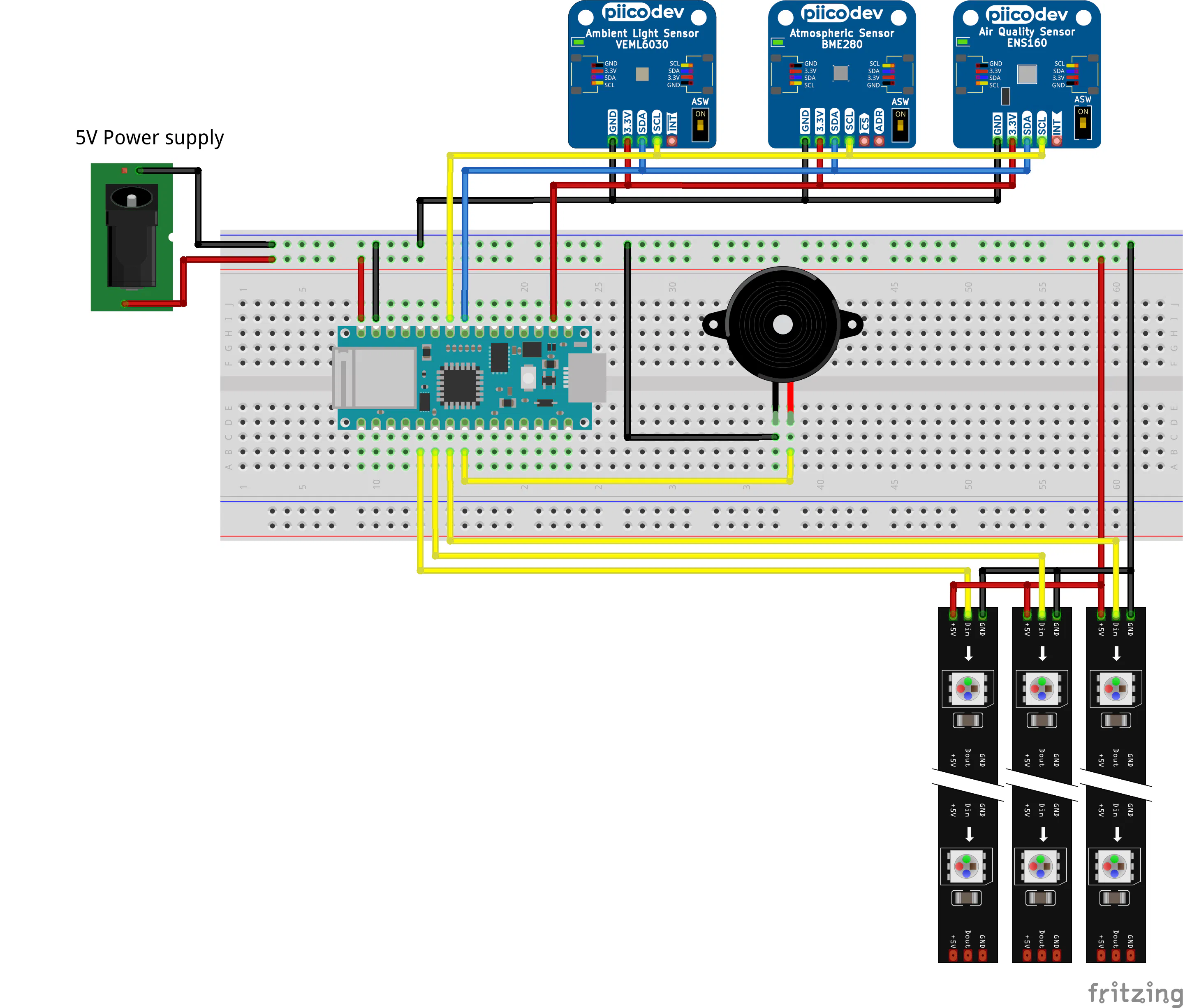
The clock is all ran from a Arduino NANO IOT 33 which has built in WiFi makes it a good choice for this project. Connected to it is the segmented display, the three I2C enviroment sensors and a buzzer. External 5v power is also supplied due to the current requirements of the NeoPixels. The display is broken into three NeoPixel strips so 3 pins are used one for each of the sections. 5 volts can be supplied by any supply that can provide enough current. To make the clock easy to power with existing systems I ended up using a USB-C downstream breakout board which gives 5v. While the IOT 33 is a 3.3v microcontroller the board has a built-in regulator to convert voltages down to 3.3v. The VIN pin can take 4.5-21v so we can just connect this pin to our 5v rail without the need for an external converter. Neopixels work fine with a 3.3v logic level so there is no need for a logic level shifer.
The sensors included are an ambient light sensor (VEML6030), air quality sensor (ENS160), atmospheric sensor(BME280). These allow us to take many readings including, tempature, humidity, pressure, CO2, TVOC, AQI and lux. To simplify the prototype I brought these sensors on piico dev breakout boards made by Core Electronics. These allow me to chain the sensors together using JST cables. In a final product all the hardware would be intergrated onto a single PCB.
Everything was assembled on a breadboard and I was now ready to move onto software. Obviously it's a bit hard to see the connections from the photo below so a Fritzing schematic is given at the end in the schematic section.
The hardware for the touchscreen component is pretty simple. I'm using a Waveshare 10.1inch Capacitive Touch Display for Raspberry Pi. The touchscreen is paired with a Raspberry Pi 4B.
The software is still a work in progress and isn't completly finalized yet but I will still share how the overall system works and some snippets of interesting parts.
Communication between the two systems is achived over WiFi using MQTT. All topics begin with the set clock ID this allows for many clocks and touchscreens to be connected through a single MQTT broker.
The controller uses the clock1/command topic to send commands to the clock. The message payload contains JSON on the command and any associated data.
The clock sends back it's sensor readings using the clock1/sensors topic. One reason I seperated out the sensors was because I thought it would make it easy for the sensor data to easily collected by external systems by just subscribing to a MQTT topic. This would make it easy to also use the data in something like HomeAssistant.
A typical sensor message looks like the following:
{"sensors":{"light":{"status":true,"lux":45},"atmosphere":{"status":true,"temp":17.61,"humid":52.43262,"press":1000.584},"airQuality":{"status":true,"TVOC":308,"CO2":804,"AQI":3}}}A command looks like this:
{"command": "SET_TIME", "data": {"time_s": 1780021512}}The current commands are SET_TIME, SET_CONFIG, SET_TIMER. When the clock recives one of the commands it updates the relevant state varibles which will then result in the clock reacting accordingly. Times are sent using unix timestamps in seconds.
A libary called Time by Michael Margolis is used to keep track of time internaly within the clock. When a SET_TIME command is recived the given timestamp is given to the time libary to set the time. It then keeps track until the next TIME_SET command. A time set command is sent from the controller once a minute. This is probably overkill since I have seen very little drift but better safe then sorry!
To keep the code clean and easy to maintain I create a kind of sensor abstraction within a seperate file which removes any complexity with reading from multiple different kinds of sensor. It also allows me to detect and attempt to recover from sensor issues. For example this is the code for the light sensor:
// --------------------------------------------------
// VEML6030
// --------------------------------------------------
bool lightSensorWorking = false;
void setupVEML()
{
    if (light.begin())
    {
        light.setGain(0.125);
        light.setIntegTime(100);
        lightSensorWorking = true;
    }
}

struct lightReading
{
    bool success = false;
    float lux = -1;
};

lightReading readLight()
{
    lightReading reading;
    if (!checkSensorAtAddress(VEML6030_ADDR))
    {
        lightSensorWorking = false;
        return reading;
    }
    if (!lightSensorWorking)
    {
        setupVEML();
    }
    reading.lux = light.readLight();
    reading.success = true;
    return reading;
}
This means all I have to call in the main file is readLight()
The Adafruit NeoPixel libary is used for NeoPixel control. Like with the sensors I create a libary to abstract away the actual individual light control so I only need to worry about the setting a digits value within the main file.
The function that sets the digits is the following:
Finaly one important part of the clock code is that I made use of task schedulering, specificly the libary taskScheduler by Anatoli Arkhipenko. This is also known as cooperative multitasking. This allows me to define methods and give them an iterval for how often they run. Then the taskScheduler runs them when needed. This is helpful as I have multiple tasks I need to do at different intervals. For example I want to update the display every 500ms and also collect and send sensor data every 5s. A task scheduler is different from a RTOS as here everything has to cooperate everything runs when needed and waits it's turn if something is already being ran. This is unlike an RTOS where tasks can have different priorities. Since most tasks take very little time and timekeeping is looked after by the built in timer this works fine for my system and allows me to avoid some of the added complexity of an RTOS.
Now moving on to the touch screen software. The touchscreen runs a single Python program which looks after the GUI and communication with the clock. A GUI libary called NiceGUI was used to create the interface. NiceGUI is infact quite nice it allows you to easily create clean GUIs and makes it easy to display values within the UI as you can bind a varible to a element then all updates to that varible will be reflected on the GUI. You can also bind values so changes to a input such as a slider automaticly update a varible.
For example here is all the code for the Config tab:
You can also see the function I created alled send_command which makes it super easy to send commands to the clock. The paho-mqtt python libary is used to look after the MQTT commuincation. This libary is nice as it allows you to start a seperate background thread to look after the connection and listen for messages meaning it doesn't interfere with the GUI ensuring it remains responsive.
The final GUI looks quite nice with minimal code. One thing that should be noted is that NiceGUI makes use of HTML and uses a browser to render the GUI similar to something like an Electron app. This does add some memory and compuation overhead but since I have a Raspberry Pi 4 dedicated to running the program it works fine. If more constrained hardware was used I'd look at a native solution.
To end off this write up here are some screenshots of the GUI.
This project is part of an assignment for Deakin University, School of IT, Unit SIT210/730 - Embedded Systems Development.


Comments