

One big challenge in exploring op amp circuits is the logistics: clearing a work space, setting up bulky supplies / signal generators or struggling with messy, intermittent wiring on solderless breadboards.
The Op Amp Discovery Board allows students, engineers and DIYers to quickly build and experiment with 20+ Op Amp configurations. Combining the best of the solderless breadboards and PCBs, this small board includes supply rails and a square-wave generator making it easy for anyone to learn on their kitchen table, in the library or coffee shop.
This is an open-source project for you to make, copy or modify for your own learning goals. (See Github link below.)
A Design Calculator (Excel) is available for 20+ circuits for you to calculate component values, gains and frequencies. Modify and expand for your own adventures.
Board OverviewThe Op Amp Discovery Board provides easy prototyping and experimenting including essential support circuitry for a stand-alone learning lab that's portable and affordable. Serves as a Trainer board as well as an Evaluation Module.
Op Amp Proto Area
- Solderless headers for easy component installation.
- PCB interconnects for versatile circuit options.
- Layout arranged like schematic to reinforce learning.
Signal Source
- Square Wave Generator
- Trimpot for Amplitude Adjust
Power Rails
- Positive and Negative Rails
- 9V Battery powered
Let’s jump in with the Non-Inverting Amplifier.
1. Review the circuit diagram.
2. Sketch out a possible build on the available headers / connections of the Proto-Area Schematic.
Install the resistors and wire jumpers - and the circuit’s ready to explore!
YOUR TURN! Print out the Proto-Area Schematic Blank (see GitHub link below) to sketch a possible build for the Inverting Amplifier. How about other classic op amp circuits - or your own circuit?
Documentation and CalculatorYou can download these handy open-source files from Github.
- User's Guide (PDF) - Self-Directed Learning
- Guided Examples ( PDF) - Walk-Through of 20 Example Circuits
- Op Amp Design Calculator (Excel) - Calculates component values, signal levels, frequencies, etc.
- Proto-Area Schematic - Blank Sheets (PDF)
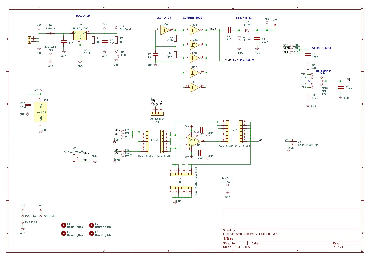
- KiCAD Project (Schematic and PCB files)
Here’s the default Parts List. Modify, customize and build it for your own learning goals.
PCB
- 3 inch x 3 inch, Circuit Board, Double Sided, KiCAD files from Github.
PASSIVES
- C10, C11, C12: 0.1uF (All caps ceramic, ≥ +25V)
- C3: 1nF
- C1, C2: 1uF
- C4, C5: 10uF
- C6, R6: Short - wires or resistor leads.
- C7, R4: Open
- D1, D2, D4: Diode 1N5711
- D3: LED Yel LTL-4253 Or any color you prefer.
- R1, R7: 1k (All resistors 1/4W, 1% preferred)
- R2, R5: 3.01k
- R3: 200k
- RV1: 1k trimpot side adjust 3352W-1-102LF
- TP1: TestPoint 5011
CONNECTORS, HEADERS
- J1: 2-pin Terminal Block screw typeOptional: Solder 9V Battery Clip Leads or Supply Leads directly to pads.
- J2: 3-pin Header TSW-103-08-T-S, Optional: for external inputs.
- J9: 2-pin Header TSW-102-08-T-S, Optional: for external output.
- JP2-JP10: 2-pin Header TSW-102-08-T-S3 shunts needed typically, SNT-100-BK-T
- J11, J12, J13: 4-pin Socket Header, SSW-104-01-T-S
ACTIVE
- U1: Op Amp LMC6081IN/NOP8, single amp, rail-to-rail output, +/-7.5V supply max, DIP. Alternate: OP07CP, single amp, precision, +/-18V supply max, DIP.
- U2: Linear Adjustable Regulator LM317LZ
- U3: Hex Inverters Schmitt Trigger 74HC14APF
SOCKETS
- U1 Socket: DIP-8 Socket 4808-3000-CP
- U3 Socket: DIP-14 socket 4814-3000-CP
PRINTED CIRCUIT BOARD (PCB)
The project was created using KiCad - a free and open-source Schematic and PCB Layout software suite. The good news is that many PCB manufacturers directly accept KiCAD files minimizing issues and errors.
SOLDERING
Assembling a board with all through-hole components is fairly strightforward. There's plenty of tutorials available online with the main points as follows: tin the solder iron tip, heat the lead and pad together, apply solder and finally briefly heat (no solder applied) until solder flows.
TESTING
Testing is easy when performed in stages (with U1 and U3 initially uninstalled.)
- Connect 9V Battery and check for +5V at U2 output (VCC).
- Install Hex Inverters U3 (with no power), check for 5V square wave, Tper = 200us. Check for -5V at VEE.
- Install Op Amp U1 (with no power), then implement a Non-Inverting Amplifier. Check the input VS and output VOUT.
- Non-Inverting Amplifier
- Inverting Amplifier
- Summing Amplifier
- Differential Amplifier
- Integrator
- Differentiator
- Wien-Bridge Oscillator
- V-to-I Converter (LED Drive)
- Sallen-Key Low-Pass Filter
- RC Comparator Oscillator
- Driving a Capacitive Load
- BJT Regulator
- Half-Wave Rectifier
- I-to-V Converter (Photodiode)
- Thermistor Preamp
What other op amp configurations do you see possible with the available component headers and interconnects?

Comments