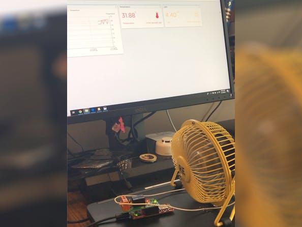
In this project, we will be extending our PIC-IoT demo project that reads the sensors on the board and sends the data to the cloud to set a temperature limit and connect a fan to maintain the temperature at the set point using the Atmosphere IoT Platform.
The PIC-IoT is based on a powerful PIC24FJ128 microcontroller. It has built-in temperature and light sensors, a mikroBUS header for expansion, a security chip, and an onboard WiFi connection.
The mikroBUS header allows the use of Click boards from MikroElektronika. We have a handful of Clicks with sensors in our element library, but for this project we will be using the Relay Click.
To use the Relay Click, you have to enable the 5VDC supply to the mikroBUS connector. There are pads next to the connector at R204 a 0 ohm resistor. It isn’t populated - you need to connect those two pads to enable the 5Vdc supply to the Click. My soldering skills are poor enough that it was easy to get a little blob of solder to bridge the pads.
If you are not familiar with the PIC-IoT, you can use our 'Getting Started with PIC-IoT' document to get up to speed quickly.
The PIC should create a drive named Curiosity when you plug it into your PC. We will use the drag and drop programming feature of the PIC to load our program on the kit.
You should also verify that you have the latest Atmosphere Agent running. The Agent is a software application that manages programming some devices and provisioning others via Serial Port.
Check the tray for the agent’s cloud icon. You can see the Developer Hub if you need additional help with the Agent.
With the Agent running, we can open the Studio, go to 'demo projects' and open the PIC-IoT onboard sensor demo.
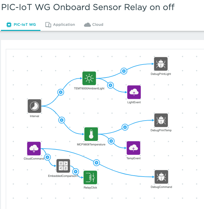
The PIC-IoT demo project uses an interval timer to take sensor readings and push them to the cloud. Because this is a WiFi connected kit, there is no mobile application, the data is sent directly to the cloud.
In the cloud, the comparison element is used to check for a Light reading value above 200 and sets the device status in the meta data to critical if true or good if false.
Now, when the light value is below 200, the device status will be good and the device color will be green and the status will change to critical and turn the device color red above 200. You can do more with alerts, including sending notifications in Studio. If you’re looking for more options, check out the added features in the Pro version.
Let’s start from the basic demo and we will show you the additional functionality we added. First we can add Debug outputs for the sensor readings. This will make it easier to see if your kit is running and sending data.
Now for the Relay Click - we have both hardware and software changes we need to make to get this working properly. First, we need to add the Click from the element library. Open the library and search for relay, Toggle the slider to enable and hit save. The element will now show up in the Imported section. Click on it to add it to the project. You will need to set up the properties of the element for use with the PIC IoT, since it can be used with any project type. The only property we need to set is the RELAY 1 GPIO PIN. For this kit the pin is P_PWM. You can find that information on the back of the PIC and in our docs on the developer hardware page for the PIC IoT: https://developer.atmosphereiot.com/documents/hardwareselection/pic-iotwg.html
Relay 2 uses a pin that conflicts with the WINC1500 WiFi module, so we can only use one relay with the PIC.
Next, we can solder wires onto the output of the fan on / off switch. By doing this we can bypass the power switch on the fan and run the power to the fan through the terminals on the Relay Click. Now with the switch on the fan off, the fan will be off when the relay is off and will turn on when the relay turns on.
We want the set point of the temperature to be adjustable from the cloud. This way we don’t have to change the code on the PIC itself once it is deployed if we decide we need to modify the set point.
To allow control from the cloud, we need to add a cloud command and connect it to a comparison element and connect that to the Click element.
First, select the cloud command from the element toolbox to add it to your project. Next, in the properties, choose a data type of integer.
Now, you can add the embedded comparison element from the embedded basic section. Set its properties for condition to equal and target value to 1.
We can also add a debug print element the cloud command, so we can see exactly what the cloud and the device should be seeing. Remember, you can’t have the terminal program open when you are trying to provision the device.
In the cloud view, we can add a condition on the temperature reading and set the temperature we want to trigger the relay to turn on.
To make it easier to see remotely what is happening at the kit, we will add a buffer element and connect it to the condition and storage.
We can set the condition to pass a 1 to the cloud command which will then be evaluated by the embedded comparison element and push the string “On” to the buffer which will then set the relay value in storage when the condition of temperature over the limit is true and a 0 and “Off” when it is false. Because the condition limit is in the cloud, we can simply change the temperature and recompile the project for the changes to take effect.
With the relay value in storage, we can set a display widget to display the fan power status, which can be viewed in the dashboard.
With our project modifications complete, we can click the Compile button to save our project and compile the code. The Atmosphere platform builds the embedded and cloud code and creates the file you need to download to your device.
The PIC-IoT has a drag and drop programming interface, so when you have compiled your project and are ready to program your kit, click on the program firmware button and drag and drop the created file onto the Curiosity drive on your PC.
The kit will program and reboot. The blue LED on the PIC-IoT should be blinking to indicate it is ready for provisioning.
The Atmosphere Agent will orchestrate the serial provisioning process for you. In the web interface, simply click on devices and then add device. Click on your device when it shows up.
The WINC1500 module doesn’t support 5GHz connections, so fill in the SSID of a 2.4GHz access point and the password, then click connect.
The green LED will stay on when it successfully connects to the access point.
You should now see a new device and be able to set up your display widgets and view your data.
We let the kit run for a little while and changed the condition set point from 32 to 34 and then to 30. You can see the effect it has on the temperature control for this particular kit.
There are lots of applications for using the PIC-IoT. You could easily use the relay to control a small light to do heating instead of cooling. Hopefully this introduction will give you more ideas and the confidence to build something amazing.
For more information, please go to our website at www.atmosphereiot.com or login and us our platform at: https://platform.atmosphereiot.com/
Richard Laborde


Comments