


Hardware components | ||||||
| × | 1 | ||||
| × | 1 | ||||
 |
| × | 1 | |||
| × | 1 | ||||
| × | 1 | ||||
 |
| × | 1 | |||
Software apps and online services | ||||||
 |
| |||||
| ||||||
Hand tools and fabrication machines | ||||||
| ||||||
This project is an application that can be realized with the tools offered by App Inventor - a platform developed by MIT which allows for developing applications for the Android operating system that can handle some tools with a smartphone such as Bluetooth, gyroscope, touch, multimedia, etc.
The main objective is to realize a system of blocking and control of a parking bar with a cellular phone. This is for when the cell is inclined towards the front the bar of block or unlocked, and when it's inclined towards the sides the bar are proportional to the angle of inclination of the cell phone.
For this project, you will work with the microcontroller PSoC 5. The purpose of this tutorial is to show one of many applications that can be made with App Inventor in conjunction with any microcontroller and make wireless applications.
The sections in which this tutorial is developed are:
- Construction of the bar
- Programming in App Inventor
- Mobile Settings
- Schematic
- Programming the micro controller
Used materials:
- Protoboard
- Lm7805
- 12v battery
- Servomotor
- Bluetooth module HC-06
- PSoC 5
- Table and stick
The servomotor to be used is the MG90S reference, but any other servomotor can be used according to the data sheet specifications.
The construction of the bar can vary according to the application you want to perform, since you can perform the same project and apply it from a toy bar to a bar the real size of a parking lot, modifying only the actuator.
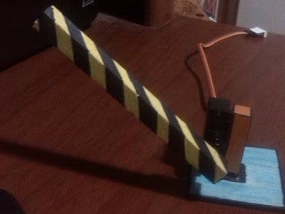
As this project is focused on programming and not on the actuator used, a small bar will be made to appreciate the operation of the project.
First we made some pieces in table and blocks as indicated in the following image.
Put the motor on one side, on the side of the stick 4 cm long. This is so that a part of the balance remains so that, when finished, it does not disturb the motor cables, as shown in the following image.
Then stick this piece to the square of 5 x 5 cm, making sure that the remaining part of the stick is attached to the board in the middle of the piece, as shown in the following figure.
Finally, we couple the bar along with the axis of the servomotor, set up as follows.
The programming made in App Inventor 2 is done through block-oriented programming; however, the concept of programming remains the same.
It is necessary to have an account associated with Google in order to use this application. Once logged in, they should start to choose the components that they want to use and create the user interface. A window will be visualized with the components that we will be adding, and another with the properties of each component, such as measurements and other characteristics.
Some components are displayed below the screen that we are editing; it means that they are internal properties of the cell that are not visible in the application, such as the internal clock, the accelerometer and the Bluetooth module.
The components section should be as follows:
It is necessary to take into account that for applications to work and be displayed without problems, you must choose boxes that allow the placement of texts and buttons in an orderly way. In these boxes, you can edit the amount of pixels they occupy in order to control the space on the screen.
Once the user interface is finished, the programming of blocks is performed; in the upper right side is the "blocks" button to change to this mode.
When you change to this mode, on the left side you will see the functions and blocks that we add to the interface. Clicking on each one of them will cause to appear the options that can be made with each one of them.
Now we just have to start programming, so we should look for the options in each one and form the code so that it is as follows.
Finally, to download the application and install it on the cell phone, we can choose two options; the first is to download the .apk file, which we can then pass to the cell by clicking on the tab "build" and then "App (save .apk to my Computer)."
Or we can generate a QR code and download an application on the cell phone that allows reading the QR code, for example, the application "BardCodeScanner" that is available in the Play Store. This code is only valid for two hours while it is being scanned.
Once the two hours have elapsed, a new QR code can be regenerated.
Section 3: Setting Up Your PhoneFirst we must make sure that the cell phone is synchronized with the Bluetooth module. For this we go to Settings, Bluetooth, and look for the device. When we try to synchronize, we will be asked for a password that is usually "0000" or "1234".
Then we need to configure the phone to be able to install the applications of unknown origin, and the applications of App Inventor can be installed.
For this we go to Settings and choose the security option.
Then select the box that says "Allow install applications that are not in Android Market".
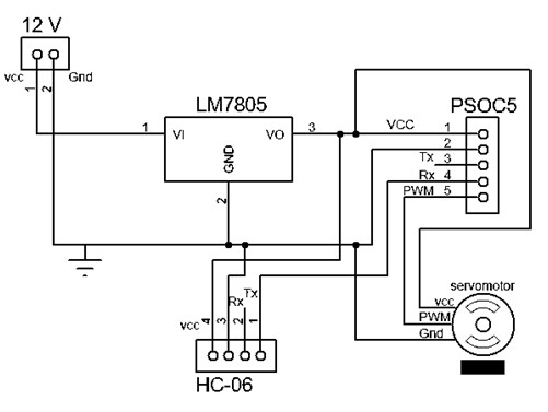
The circuit assembly consists of a servomotor and a Bluetooth module, so it is not complex to perform.
The Bluetooth Tx pin is wired with the Rx pin that was configured on the PSoC (pin P12 [7]).
The output to the servomotor is by the pin configured in the PSoC (pin P0 [1]).
The function of the microcontroller in this project is to receive the order of graduated opening of the bar, so we will constantly be reading the data that we send from the cell.
This project can be done with any microcontroller, for this case we will use a PSoC 5. We must have previously installed Creator; I use Creator 3.0, but you can also use in other versions, and you can download it for free from the following page. Http://www.cypress.com/documentation/software-and-drivers/psoc-creator-software-archive
We open a new project and select PSoC 5 and the reference of the card, which is printed on the microcontroller.
In the following image are all the programmable blocks that PSoC handles:
First, we have to add a UART block that is in the communications folder, and we configure it as follows:
Next, we add a PWM block (it is in the "Digital" folder), a clock block "Clock" (it is in the "system" folder) and configure it as follows.
It is important that the period be of 20 ms, since the servomotors that we are going to use handle this frequency. In case of a different servomotor, this parameter must be adjusted by modifying the value of the clock block "Clock" or the value of the period of the PWM "Period".
Now double click on "main" to write the code and in ".cydwr" to select the pins.
To configure the pins, the following window will appear.
Select the pins as follows:
- Pin_1 en el pin P0 [1]
- Rx_1 en el pin P12 [6]
- Tx_1 en el pin P12 [7]
Now, we go to the main window and write the following code:
Note: it is advisable to first check the direction of rotation of the servomotor. For this, we will remove the bar with the shaft and verify that it is rotating correctly without problems of collisions. In case the direction of rotation is inverted, we will only change the order of the numbers, leaving them as follows.
If (dato==’a’) { PWM_WriteCompare(193); }
If (dato==’b’) { PWM_WriteCompare(193); }
If (dato==’c’) { PWM_WriteCompare(192); }
If (dato==’d’) { PWM_WriteCompare(191); }
If (dato==’e’) { PWM_WriteCompare(190); }
If (dato==’f’) { PWM_WriteCompare(189); }
If (dato==’g’) { PWM_WriteCompare(188); }
If (dato==’h’) { PWM_WriteCompare(187); }
If (dato==’i’) { PWM_WriteCompare(186); }
If (dato==’j’) { PWM_WriteCompare(185); }
If (dato==’z’) { PWM_WriteCompare(193); }
Finally, compile by clicking the next button.
And it should not generate any errors.
In this way, we will be receiving the operating instructions for the bar.
You only need to burn the program in PSoC 5, which will only connect the card directly to the PC and click on the next button.
Now it is only necessary to rehearse the entire program as a whole.


Comments