

Hardware components | ||||||
| × | 1 | ||||
| × | 1 | ||||
| × | 1 | ||||
 |
| × | 4 | |||
Software apps and online services | ||||||
 |
| |||||
Hand tools and fabrication machines | ||||||
 |
| |||||
Digital rain, or “Matrix Code”, is an animated visualization featured throughout The Matrix movies. With its distinct green color and cyberpunk feel, it has become iconic in pop culture.
In this visual effect, columns of random text characters continuously rain down from the top of the image frame. The streaming motion and trailing colors of many falling drops become captivating to watch.
This project demonstrates how to build a desktop clock that displays the time against a digital rain background. Users can enjoy ambient visuals of the rain and use touch interactions to set the time and change its color.
Clock FeaturesThe digital rain clock is designed as a functional desktop accessory, combining practical timekeeping with a dynamic, eye-catching visualization.
It features a touchscreen display and integrated control electronics mounted to a custom 3D-printed stand. These electronics are intentionally exposed behind the screen to emphasize a maker-style aesthetic.
Once powered via USB, the clock renders a digital rain animation consisting of trails of randomized characters cascading vertically down the screen at varying speeds.
At the start of each minute, the current time is overlaid at the center of the screen. After several seconds, the digits gradually dissolve as streaks of digital rain overwrite them. Tapping the center of the screen brings the time back into view on demand.
Adjusting the current time is done by tapping the top-right corner to open a menu with touch controls for changing the hour and minute values. Tapping the same corner again closes the menu and displays the updated time.
The color of the digital rain and time are updated by tapping the bottom-left corner of the screen. Each tap cycles the interface through green, red, blue, yellow, and purple color schemes.
The physical build of the digital clock consists of multiple electronic components and a 3D printed structural stand.
An Adafruit 2.8" TFT breakout board serves as the display that shows the clock face. The board includes a 240x320 pixel full-color display and capacitive touchscreen that detects user touches.
EYESPI is a connection standard developed by Adafruit to simplify the wiring of its displays, which replaces multiple jumper wires with a single flexible ribbon cable.
This standard is utilized by connecting the TFT to an Adafruit EYESPI breakout board via an 18 pin FPC. The board exposes the display's SPI, backlight, power, and touch interrupt pins through onboard header pins.
An Arduino Nano ESP32 acts as the clock's primary processor and power source. It connects to the display via the EYESPI breakout and executes custom firmware that manages the rain animation, maintains clock timing, and handles touchscreen input.
The Nano and EYSPI breakout are wired together on a breadboard that sits within the stand base, while the display is mounted to the upright stand face. The stand face pressure-fits within a slot on the base.
Once fully assembled, the Nano ESP32 is powered via its USB-C port, which distributes power to the display and initializes the clock firmware.
Build InstructionsBelow are instructions on how to construct and program the digital rain clock. These instructions assume working knowledge of the Arduino Nano ESP32 and the Arduino IDE.
Complete project code and 3D print files are found within this project's attachments and on GitHub.
Hardware SetupBegin the build by first assembling the clock's electronics and installing them within the custom stand.
1. 3D print the clock stand
The stand includes two separate parts - a base and face plate. 3D model files (.stl) for both parts are provided in this project's attachments.
PLA is the recommended material for these prints.
2. Solder the jumper pads on the TFT display
To enable communication via the EYESPI connector, the TFT display must be set to SPI mode by connecting its hardware mode selection jumpers to 3.3V.
Use a soldering iron to create solder bridges across the IM1, IM2, and IM3 pads found on the back of the breakout board. Closing these specific jumpers configures the display for the correct communication standard.
3. Build the electronics circuit
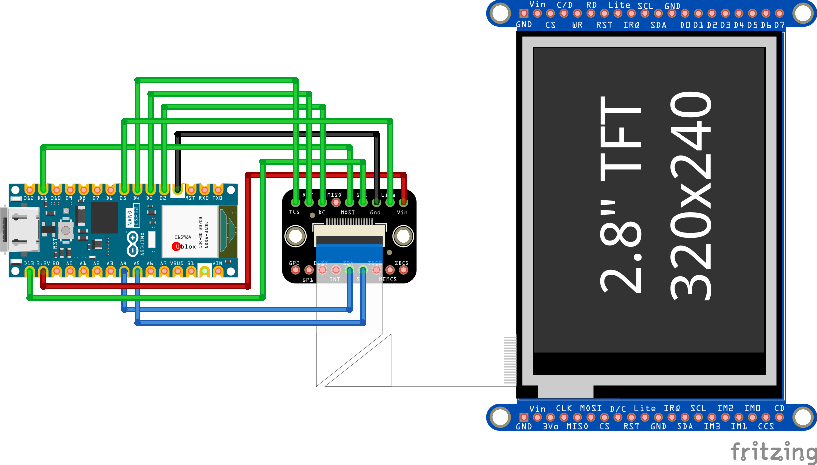
Seat the Arduino NanoESP32 and EYESPI breakout board on a 400-point solderless breadboard, then use jumper wires to create the pin connections seen in the circuit diagram below:
The breadboard layout should resemble the following:
4. Mount the electronic components
Fit the breadboard into the recess of the base. Then, align the TFT touchscreen mounting holes with the faceplate standoffs and secure them with four M3x4 screws.
5. Wire the display and finish assembly
Connect the TFT touchscreen to the electronics using the EYESPI cable. Insert one end of the FPC into the flip-top connector on the back of the touchscreen, and the other end into the connector on the EYESPI breakout board.
Next, attach the two parts of the stand by sliding the bottom edge of the face plate into its receiving slot on the base.
With these steps complete, the hardware is fully assembled and ready for firmware upload.
Firmware SetupThe clock is driven by a custom Arduino sketch that executes on the Arduino Nano ESP32 each time the device is powered on.
This firmware manages all device functionality, including drawing the graphical user interface, animating the digital rain, calculating precise timing, and interpreting touch input from the user.To run this firmware, the Nano ESP32 must be properly configured and have the Arduino sketch uploaded to it.
1. Install required Arduino libraries
For the Arduino code to perform complex actions like drawing to the TFT display and processing touch inputs, it requires access to additional code provided by several external libraries.In the Arduino IDE, open the Library Manager (Tools -> Manage Libraries), then search for and install the following libraries:
- Adafruit GFX Library - The core graphics provider for shapes and text.
- Adafruit ILI9341 - The driver for the 2.8" TFT display.
- Adafruit FT6206 Library - The driver for the capacitive touchscreen.
- ESP32Time - A library to manage the ESP32’s internal real-time clock.
Note: If prompted to install dependencies (such as Adafruit BusIO), select "Install All" to ensure everything functions correctly.
2. Upload the Firmware
Download the DigitalRainClock.ino sketch from the GitHub repository linked in this project's attachments and open it in the Arduino IDE.
Connect the Nano ESP32 to the computer via USB-C. Under the Tools menu in the IDE, ensure the Board is set to 'Arduino Nano ESP32' and the corresponding Port is selected. Click the Upload arrow to compile the code and transfer it to the board.
After upload the sketch will automatically execute each time the Arduino Nano ESP32 receives power.
With these build instructions complete, the working digital clock is ready to be displayed and utilized as a functional desktop accessory.


Comments